Disassembly, Reassembly and Lubrication
CL-S6621 3-52
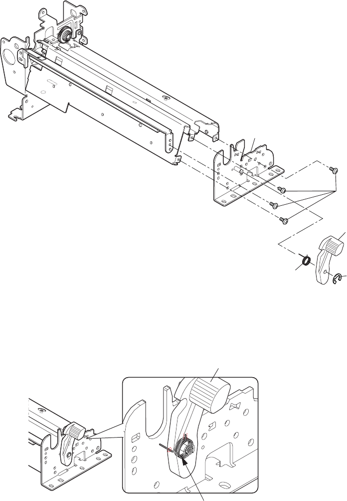
3-6-22. “Lever Head Lock” and “SA Main Frame R”
1. Remove the “Unit, Mechanism”. Refer to “3-6-13(1) Unit, Mechanism”.
2. Remove the “SA, PF Motor”. ”Refer to “
3-6-19 SA PF Motor”.
3. Remove the “Carriage Adjust Sensor L” and “SA, Head Up Switch”. Refer to “
3-6-20(1)
“Carriage Adjust Sensor L” and “SA, Head Up Switch””.
4. Remove the 4 screws (BH, M3x4 (NI)) and detach the “SA Main Frame R” Block.
5. Disengage the “E-Ring, 2.5”, and remove the “Lever Head Lock” and “Spring Head Lock” from
the “SA Main Frame R”.
Note on reassembling:
• When assembling the “Lever Head Lock”, hook the “Spring Head Lock” as shown below. (Shorter
end is inserted into the groove of the “Lever Head Lock” and the longer end into the frame hole.)
Lever Head Lock
Spring Head Lock
SA Main Frame R
BH, M3x4 (NI)
Lever Head Lock
Spring Head Lock
E-Ring, 2.5


