


Operation of Control Parts
2-37 CL-S6621
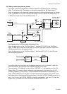
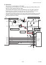
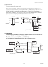
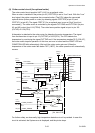
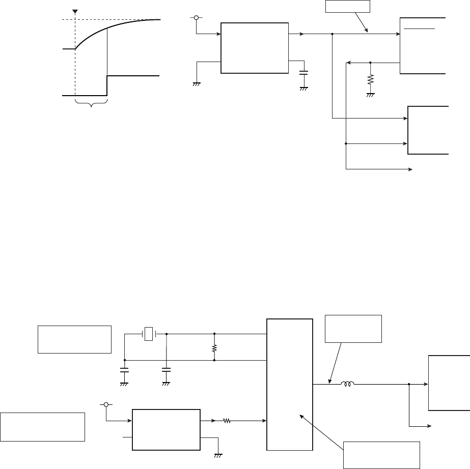
(2) Reset circuit
This circuit performs the system reset.
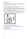
When power is turned ON, +3.3V increases gradually from 0V. When the voltage at pin 2
(+3.3V) of U6 (Voltage detector) reaches approx. at 2.8 V, nRESET33 signal goes from “Low”
to “High” level after a certain delay time (determined by C7 at pin 5 of U3) has passed.
While nRESET33 signal is “Low”, U1A (CPU) and U14 (FPGA) are reset. Also, by nGRESET
signal output from U1A (CPU), U14 (FPGA) and other circuits are reset.
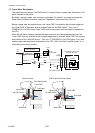
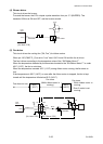
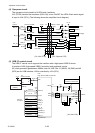
(3) Clock circuit
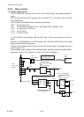
Crystal oscillator X1 oscillates a 16 MHz clock. This clock is send to U1A (CPU) and the CPU
generates a 128 MHz internal clock and 64 MHz clock.
The 64MHz clock is fed to U14 (FPGA) and U13 (SDRAM)
X2 (Clock generator) oscillates a 48 MHz clock used for optional I/F control.
VSS
+3.3V
5
3
1
Voltage Detector
nRESET33
RESET
L : Reset
G13
U1A
CPU
B3_17
U14
FPGA
Power ON
Reset
+3.3V
+3.3V
H
L
0V
P52
nGRESET
nGRESET
C14
B3_1
nRESET33
nGRESET
nRESET33
U6
S-1009C28I-M5T1U
OUT
CD
VDD
2
28
23
C7
R5
[SA, Main PCB]
U1A
CPU
U14
FPGA
X1
R1
C2
System Clock
(16MHz)
BUSCLK
PCD1
88
B3_6
D15
G
+3.3V
Clock Generator
Clock for optional I/F
(48MHz)
X2
V
DSC8002DI1(48MHz)
SB
C
Bus Clock
(64MHz)
Internal Clock
(128MHz)
P10
159
C1
BUSCLK
[SA, Main PCB]
4
1
3
2
R11
R2
16MHz
X1
164
X2
165