


Disassembly, Reassembly and Lubrication
CL-S6621 3-50
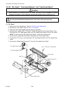
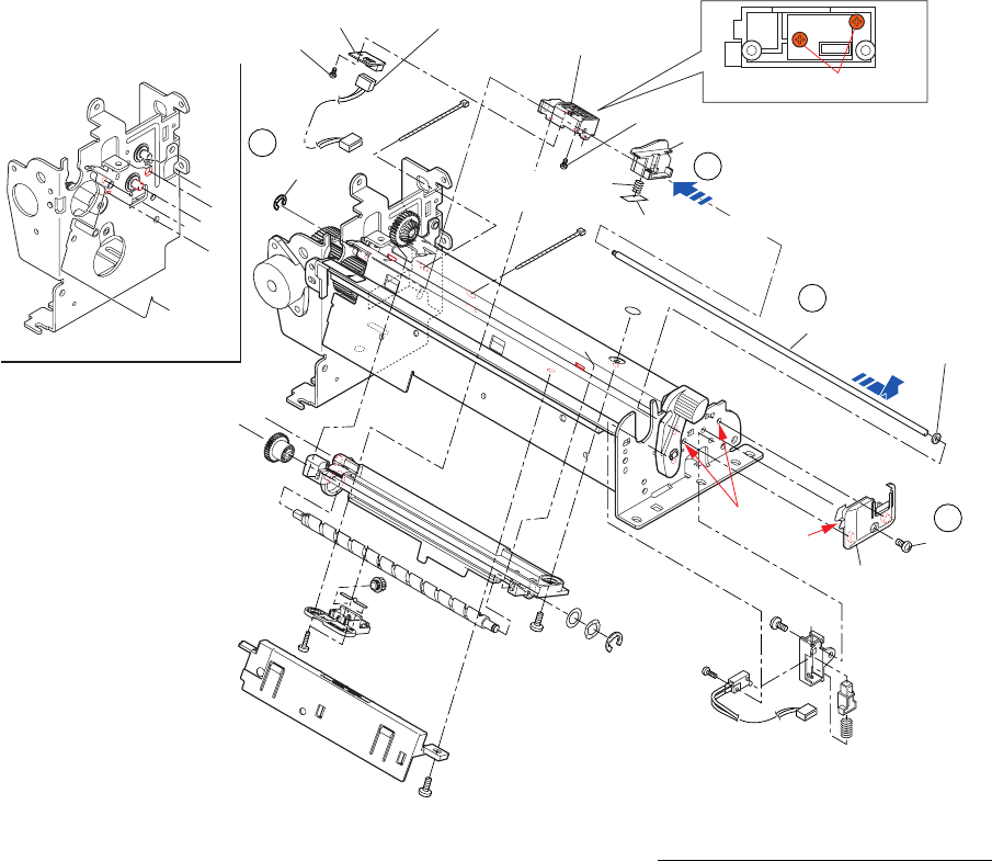
Shaft Sensor Guide
Holder Adjust Sensor L
Guide Paper R
SA Ref Sen PCB
No.0 PHT (BT#1) M2x3
No.0 PHT (BT#1) M2x3
SA, Ref Sensor Cable
Spring Friction
Sen PG
Plate Function PG
b
b
c
c
a
a
d
BH, M3x4 (NI)
Spacer Guide Shaft
Holder, Guide Sensor L
E-ring, 1.5
a
[Bottom View]
No.0 PHT (BT#1) M2x3
8
9
A
B
10
7
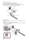
(2) SA Ref Sen PCB
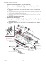
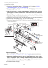
1. Remove the “Carriage Adjust Sensor L”. Perform steps 1 to 7)-2 in above “3-6-20(1)
“Carriage Adjust Sensor L” and “SA, Head Up Switch””.
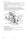
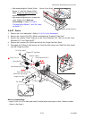
2. Disengage the “E-Ring, 1.5” (), remove 1 screw (BH, M3x4 (NI)) (), and detach the
“Holder, Guide Sensor L”.
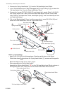
3. Slide the “Guide Paper R” () to the left and remove the “Shaft Sensor Guide” () in the
direction shown by the arrow, together with the “Guide Paper R” Block and “Holder Adjust
Sensor L” Block.
4. Remove the “Spacer Guide Shaft”, and then pull out the “Guide Paper R” Block and “Holder
Adjust Sensor L” Block from the “Shaft Sensor Guide”.
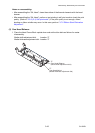
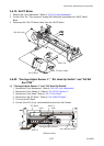
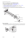
5. Remove the “Spring Friction Sen PG” and the “Plate Friction PG” from the “Guide Paper R”.
6. Disconnect the “SA, Ref Sensor Cable” from the “SA Ref Sen PCB”.
7. Remove the 2 screws (No.0 PHT (BT#1) M2x3) and detach the “SA Ref Sen PCB” from the
“Holder Adjust Sensor L”.
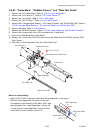
Notes on reassembling:
• When the “SA Ref Sen PCB” is replaced with new one, perform the sensor adjustment.
Refer to “
3-7-1 Transparent/Reflective Sensor Position Adjustment”.
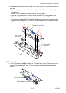
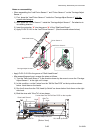
• Assemble the “Shaft Sensor Guide” () (with the “Holder Adjust Sensor L” Block, “Guide,
Paper R” Block and the “Spacer Guide Shaft”), and align its ends in places. Next, assemble
the “Holder, Guide Sensor L”. (Its groove “A” should engage with the frame plate. Also its
protrusions should be inserted into the holes “B” in the frame.)
(to be continued on the next page)