Operation of Control Parts
2-41 CL-S6621
J10
Cutter Control Circuit
3
2
1
5
4
7
6
8
10
9
VMT
U1A
CPU
D20
CPRTYP0
PCT2
81
R82
C101
R85
+3.3V
CUTTMP
(PEELSENS)
ANI7
12
Q11
DTC114EM
(Analog Switch)
4
1
2
U5
R84
+3.3V
L: When Cutter installed.
Switch: ON (Fixed)
R77
+3.3V
C98
R79
C100
R81
+3.3V
U14
FPGA
RA18
N2
CUTCON0
N1
B1_33
B1_34
CUTCON1
+24V
+24V
CUTCTL0
CUTCTL1
CUTHP
CUTTH
GND
GND
GND
CPRTYP0
CUTHP
118
U17B
BA2903SFV
-
+
5
6
7
+3.3V
R39
+3.3V
R40
C41
R41
R42
C11
C6
B2_28
B2_27
U14
FPGA
nTEMP_ERROR
nTEMP_ENABLE
CUTTMP
[SA, Main PCB]
TEMP ERROR Detection
CUTTMP
(+24V)
Error: Low
CPRTYP1
PCT3
80
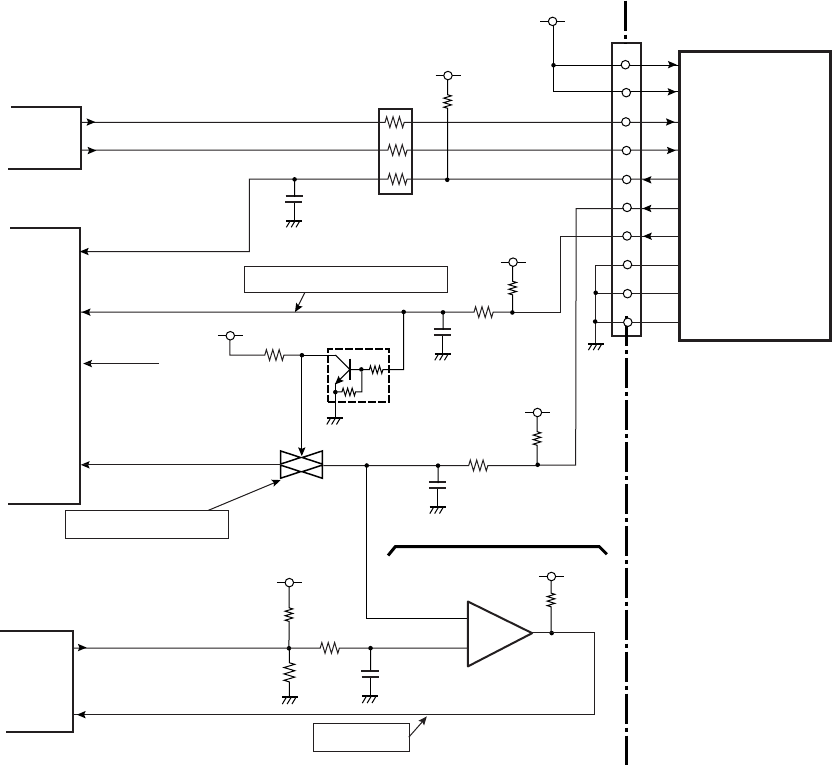
(9) Cutter control circuit (for optional cutter)
The cutter control circuit supplies VMT (+24V) to an optional cutter.
When a cutter is installed in the printer, pin 81 (CPRTYP0) is set to “Low” level. With this “Low”
level signal, the printer recognizes the connected cutter. (The CPU judges the connected
optional device (either peeler or cutter) by detecting signals CPRTYP0 (at pin 81) and
CPRTYP1 (at pin 80). The signal CPRTYP1 for an optional peer is now at “High” level (not
connected). ) The cutter action is controlled by the signals CUTCON0 and CUTCON1 (at pins
N1 and N2) output from U14 (FPGA). The cutter home position signal is input to pin 118
(CUTHP) of U1A (CPU).
A thermistor is attached to the cutter motor for detecting the motor temperature. The signal
from the thermistor is input to pin 12 (CUTTMP) of U1A (CPU). The CPU detects the
temperature by monitoring the signal CUTTMP and, if the temperature reaches 78
°C (108.4°F),
the cutter motor stops its operation. At this time, an error is issued and the PRINT LED and
CONDITION LED blink alternatively. Wait until the cutter motor gets cool. When the
temperature of the cutter motor falls below 70°C (185°F), the cutter operation will automatically
resume.
For further safety, an abnormally high temperature detection circuit is provided. In case this
circuit is activated, the System error is displayed, and the printer stops.


