


Operation of Each Mechanism
CL-S6621 2-10
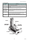
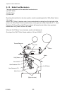
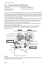
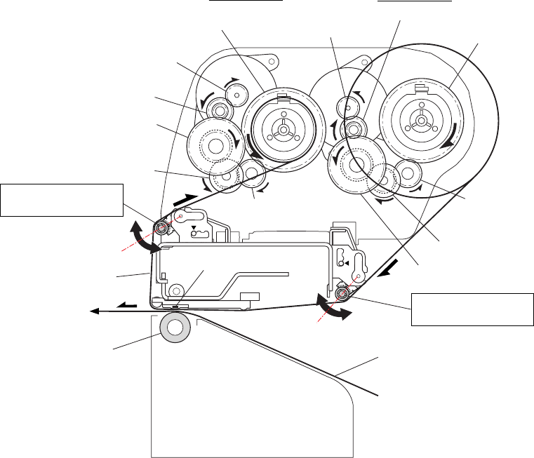
SA2_Platen
Media
Ribbon
Thermal Head
SA, Ribbon Tension
Shaft F
SA, Ribbon Tension
Shaft R
Take-up Side
Supply Side
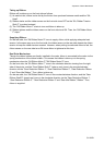
Gear Ribbon Shaft R
Gear Ribbon Shaft F
SA Ribbon Motor R
SA Ribbon Motor F
Gear Reduction Ribbon 1
Gear Reduction Ribbon 1
Gear Reduction Ribbon 2
Gear Reduction Ribbon 2
Gear Reduction Ribbon 3
Gear Reduction Ribbon 3
Gear Idle Ribbon
Gear Idle Ribbon
[Front]
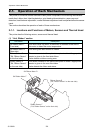
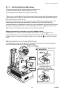
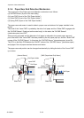
2-1-4. Printing and Ribbon Feed Mechanism
The major components of the printing and ribbon feed mechanism are:
(a) SA, Head (d) SA, Ribbon Tension Shaft F/R
(b) SA Ribbon Motor F/R (e) SA, Ribbon Sensor (Front/Rear)
(c) Ribbon gear train
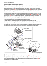
Ink ribbon is set to the printer using the ribbon holders. Ribbon is supplied from the supply reel and
is taken up by the take-up reel with adequate ribbon tension, via the “SA, Ribbon Tension Shaft R”
and “SA, Ribbon Tension Shaft F”. The “SA, Ribbon Tension Shaft F/R” is always pushed outward
by the internal springs, and, when ribbon slacks, it moves outward. When ribbon tightens, it moves
inward. (Refer to the figures on the later pages.)
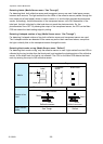
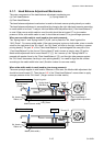
The same ribbon sensor is installed on the front and rear sides. The ribbon sensor on the front side
is used to detect the position of the “SA, Ribbon Tension Shaft F” (i.e., the ribbon tension on the
front side). While, the ribbon sensor on the rear side is used to detect the position of the “SA,
Ribbon Tension Shaft R” (i.e., the ribbon tension on the rear side).
The ribbon sensor on the front side is also used to detect a ribbon running condition, and that on
the rear side is used to detect the ribbon end.
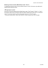
On the front side, the “SA Ribbon Motor F” turns to take up ribbon. On the rear side, the “SA
Ribbon Motor R” turns to supply ribbon, while applying adequate back tension to ribbon to
eliminate ribbon slack.
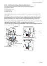
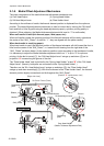
Printing:
When printing with ink ribbon, ink on the ribbon is melted by the heated thermal element of the “SA,
Head” and is transferred on the media surface.