


Operation of Control Parts
CL-S6621 2-40
[SA, Main PCB]
3
2
J13
1
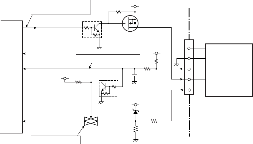
Peeler Control Circuit
Q15
DTC115EM
PWRSAVE
U1A
CPU
D18
114
L: Power Saving mode
H: Normal mode
+5V
Q14
2SJ625
CPRTYP1
PCT3
80
5
4
R83
C102
R86
+3.3V
D4
R87
R92
+3.3V
R93
PEELSENS
(CUTTMP)
ANI7
12
Q16
DTC114EM
(Analog Switch)
4
1
2
U3
R88
+3.3V
L: When Peeler installed.
Switch: ON (Fixed)
NC
GND
CPRTYP1
+5V
PEELSENS
PEELSENS
CPRTYP0
PCT2
81
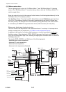
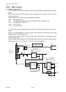
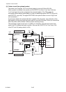
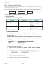
(8) Peeler circuit (for optional peeler)
The peeler circuit supplies +5V to an optional peeler by turning Q15 and Q14 ON.
When a peeler is installed in the printer, pin 80 (CPRTYP1) is set to “Low” level. With this
“Low” level signal, the printer recognizes the connected peeler. (The CPU judges the
connected optional device (either peeler or cutter) by detecting signals CPRTYP0 (at pin 81)
and CPRTYP1 (at pin 80). The signal CPRTYP0 for an optional cutter is now at “High” level
(not connected). )
A peel sensor detects the printed label that is peeled off by the peeler. Upon detection of the
label peeled, printing stops and the printer waits for removal of the label. When you remove the
label, the peeler sensor detects it and the printer resumes printing.
The peel sensor signal is input to pin 12 (ANI7) of U1A (CPU). From the input level of this
signal, the CPU detects the peeler condition. (Since pin 80 (CPRTYP1) is “Low” level, Q16
turns OFF and U3 (analog switch) is ON.)