


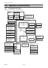
Operation of Control Parts
2-25 CL-S6621
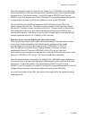
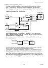
When the transparent sensor is conducted, the voltage at pin 5 (TRAMON) varies depending
on the characteristics of the light receiving element (phototransistor) of the transparent sensor
and other factors. To solve this problem, U14 (FPGA) outputs TSNSCTL0 (pin R13) and
TSNSCTL1 (pin R14) signals to turn ON/OFF Q8 and Q7 to connect/disconnect R69 and R68
(voltage dividing resistors) to minimize the difference in level at pin5 (TRAMON).
The current flowing into the LEDs is determined by the data sent from the CPU to the
digital-to-analog converter (U7). The digital-to-analog converter converts the data received
from the CPU, and then outputs a resoultant level at pin 2. The base current of the transistor
Q6 is determined by this level. This means that the current flowing into the LEDs is also
determined by this level. In the actual control, the CPU changes data (for controlling the LED
current) to keep the level at pin 5 (TRAMON) of CPU constant.
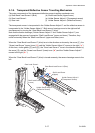
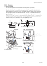
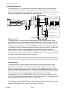
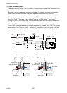
Reflective sensor (used for detecting the black mark on tag):
When tag with black marks is used, light is reflected by the tag. In the place where no black
mark is there, the phototransistor of the reflective sensor conducts and the voltage
corresponding to the amount of light is applied to pin 6 (REFMON) of U1A (CPU).
When the light falls on the black mark, no light is reflected. In this case, the lower
phototransistor turns OFF and pin 6 (REFMON) of U1A (CPU) will go “Low” level.
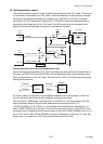
When media runs out, the light is not reflected and no light falls on the reflective sensor. In this
case, pin 6 (REFMON) of CPU will go “Low” level and media end is detected.
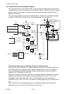
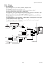
When the reflective sensor is conducted, the voltage at pin 6 (REFMON) varies depending on
the characteristics of the light receiving element (phototransistor) of the reflective sensor and
other factors. To solve this problem, U14 (FPGA) outputs TSNSCTL0 (pin R13) and
TSNSCTL1 (pin R14) signals to turn ON/OFF Q10 and Q9 to connect/disconnect R75 and R74
(voltage dividing resistors) to minimize the difference in level at pin6 (REFMON).
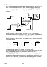
As to the current control of the LEDs, the operation is the same as for the transparent sensor
mentioned above.