Disassembly, Reassembly and Lubrication
3-41 CL-S6621
3-6-17. Unit, Head
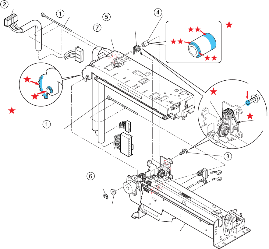
1. Remove the “Unit, Mechanism”. Refer to “3-6-13(1) Unit, Mechanism”.
2. Cut the “Wire Tie” (2 pcs.) () and remove the “SA, Ribbon Cable” ().
3. Open the “Unit, Head” and remove the 1 screw (PH (SW+PW), M4x16) (), then remove the
“Shaft Head Holder” () and “Spring Ribbon Unit Dumper” ().
4. Disengage the “E-ring 4” (), remove the “Bush Head Holder”, and detach the “Unit, Head”
(
) from the “Unit, PF”.
Notes on reassembling:
• Apply FLOIL G-311S to the following places. (See the mark
Ì shown in the figure.)
A: Hole (front left). Circumference surface of the hole (on both sides) and inside the hole
B: Along the rack part.
C: 3 surfaces on the “Shaft Head Holder” ().
D and E: Both ends of the “Spring Ribbon Unit Dumper” ().
• Apply adhesive LOCTITE263 to the end (F) of screw (PH (SW+PW), M4x16) ().
• When assembling the “Shaft, Head Holder” (), be sure that its assembling direction is correct.
(See the magnified view.)
• Set the “Spring Ribbon Unit Dumper” ( as shown in the magnified view. Insert its rear end to
the opening “D”. Other end is a free end.
Wire Tie
Wire Tie
SA, Ribbon Cable
Shaft Head Holder
Spring Ribbon
Unit Dumper
PH (SW+PW), M4x16
E-Ring 4
Position here.
Free end
Unit, Head
Unit, PF
FLOIL G-311S
FLOIL G-311S
[When assembling]
Bush Head Holder
Spring end
J5
J3
J6
J7
J8
J11
J19
C
A
B
D
LOCTITE263
E
F


