


Operation of Control Parts
CL-S6621 2-36
7
6
9
4
5
8
J15
4
3
+24V
+1.5V
+3.3V
[SA, Main PCB]
Q19
DTC115EM
U1A
CPU
D18
114
+5V
C106
C105
+
VIN
LX
FB
3
5
2
U22
DC-DC Converter
R1243S001C
VIN
SW1
SW2
SW3
FB
13
4
10
U24
DC-DC Converter
PAM2307AJEADJR
VIN1
VIN2
LX1
FB1
LX2
FB2
8
4
7
U23
DC-DC Converter
PAM2306AYPCB
1
2
10
+1.2V
Q22
+3.3V
Q23
+5V Regulator
+3.3V Regulator
+1.5V/+1.2V Regulator
+5V
PWRSAVE
2
1
L: Power Saving mode
H: Normal mode
PVIN1
PVIN2
PVIN3
11
12
9
15
14
From
Unit, Power
Supply
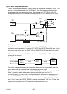
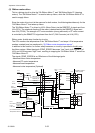
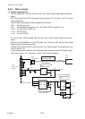
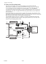
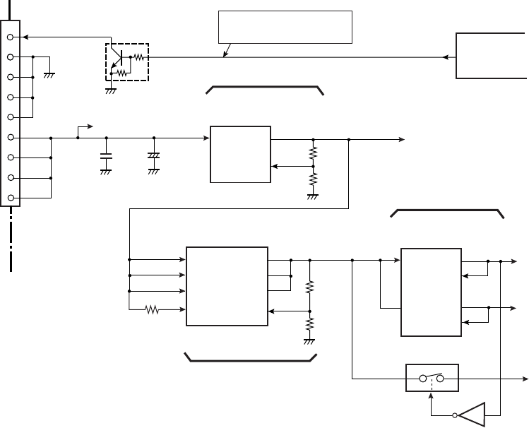
2-2-5. Other circuits
(1) Power supply circuit
The “SA, Main PCB” receives +24V from the “Unit, Power Supply” and produces each DC
power.
U22, U24 and U23 are DC-DC converter ICs to produce +5V, +3.3V and +1.5V/+1.2V from
+24V, respectively.
The DC power produced and their purposes are as follows:
+24V: For driving circuits
+5V: For transparent/reflective circuit, “SA, Ribbon PCB”, optional I/F, etc.
+3.3V: For logic circuits, LED, etc.
+1.5V: For U1 (CPU)
+1.2V: For U14 (FPGA)
If +1.5V for CPU is not produced, Q22 turns OFF and +3.3V for logic circuits is shut off for
safety.
When pin 114 (PWRSAVE) of U1A (CPU) goes “Low”, Q19 turns OFF and the “Unit, Power
Supply” enters Power Saving mode.
In Power Saving mode, the DC output from the “Unit, Power Supply” is changed over from
+24V to approx. +9V.
(Power saving mode is effective if the “Standby Mode” submenu under the “System Setup”
main menu is set to “On”. However, it is set to “Off” at factory default.)