


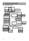
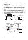
Operation of Control Parts
CL-S6621 2-26
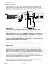
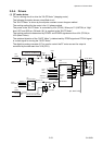
(SA, Ribbon Sensor)
Ribbon Sensor1
2
3
1
PT501
PS501
R501
4
Front (Take-up side)
2
3
1
4
Rear (Supply side)
2
3
1
J104
4
(Same as above circuit)
PT501
2
3
1
J105
4
[SA, Ribbon PCB]
+3.3V
14
13
J102
U1A
CPU
34
PCM0
14
13
32
PCM2
J19
16
15
31
PCM3
16
15
29
PCM5
Ribbon Sensor2
PS502
R502
(SA, Ribbon Sensor)
+3.3V
1
1
+3.3V
+3.3V
SENS_A1
SENS_A2
SENS_B1
SENS_B2
C175
RIBSENS_A1
RA20
5
6
U21C
C176
C177
C178
R136
R137
R138
R139
9
8
U21D
11
10
U21E
13
12
U21F
RIBSENS_A2
RIBSENS_B1
RIBSENS_B2
U2A
U2B
U2C
U2D
2
3
5
6
9
8
12
11
[SA, Main PCB]
18-20 18-20
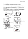
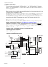
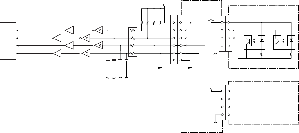
(3) Ribbon Sensor F/R
The ribbon sensor F (“SA, Ribbon Sensor” mounted on the front side) is used to detect the
ribbon tension on the front side as well as ribbon running. While, the ribbon sensor R (“SA,
Ribbon Sensor” mounted on the rear side) is used to detect the ribbon tension on the rear side
as well as the ribbon end. These sensors are photointerrupters.
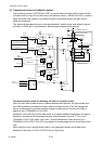
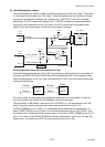
Ribbon sensor F:
The ribbon sensor F is used to keep the ribbon tension on the front side constant. When
printing starts, ribbon is fed and then the front side ribbon slacks. Then, the claws of the “SA,
Ribbon Tension Shaft F” come off the photointerrupters on the “SA, Ribbon Sensor” and the
photointerrupters turn ON. Thus, pin 34/32 (RIBSENS_A1/A2) of U1A (CPU) goes "High" level.
In this case, U1A (CPU) increases the revolution speed of “SA Ribbon Motor F” to take up the
slack of ribbon. As a result, ribbon tightens and the claws are inserted into respective
photointerrupters. Thus, pin 34/32 (RIBSENS_A1/A2) of U1A (CPU) goes "Low" level. Then,
U1A (CPU) slows down the revolution speed of “SA Ribbon Motor F”. During printing, this cycle
is repeated and constant ribbon tension is maintained.
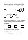
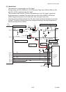
If ribbon is not correctly fed during printing, the ON/OFF state of the photointerrupters on the
“SA, Ribbon Sensor” becomes improper. Thus, the CPU can detect an abnormal ribbon feed.
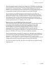
Ribbon sensor R:
The ribbon sensor R is used to keep the ribbon tension on the rear side constant. When
printing starts, ribbon is fed and the rear side ribbon tightens. Then, the claws of the “SA,
Ribbon Tension Shaft R” are inserted into respective photointerrupters on the “SA, Ribbon
Sensor” and the photointerrupters turn OFF. Thus, pin 31/29 (RIBSENS_B1/B2) of U1A (CPU)
goes "Low" level. In this case, U1A (CPU) increases the revolution speed of “SA Ribbon Motor
R” to supply ribbon faster. As a result, ribbon slacks and the claw comes off the
photointerrupter. Thus, pin 31/29 (RIBSENS_B1/B2) of U1A (CPU) goes "High" level. Then,
U1A (CPU) slows down the revolution speed of the “SA Ribbon Motor R”. During printing, this
cycle is repeated and constant ribbon tension is maintained.
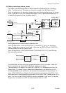
When ribbon runs out, the ON/OFF state of the photointerrupters on the “SA, Ribbon Sensor”
becomes unchangeable. Thus, the CPU can detect the ribbon end.