


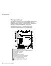

Setting System-Board Configuration Jumpers
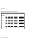
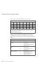
Table 14 shows the default SCSI IDs for hot-swap drives.
Table 14. Default SCSI IDs for Hot-Swap Drives
J3
Pins
J4
Pins
Bay 1
or 7
Bay 2
or 8
Bay 3
or 9
Bay 4
or 10
Bay 5
or 11
Bay 6
or 12
1-2 1-2 0 1 10 3 4 13
1-2 2-3 0 1 2 3 4 5
1
2-3 2-3 8 9 2 11 12 5
1
2-3
2
1-2
2
8 9 10 11 12 13
Notes:
1. See “Setting SCSI IDs for External Devices” on page 209 for rules about
setting SCSI IDs for devices.
2. This is the default jumper setting.
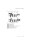
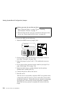
Setting System-Board Configuration Jumpers
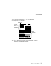
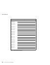
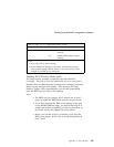
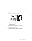
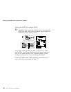
Table 15 summarizes the settings for the system-board configuration
jumpers.
Table 15 (Page 1 of 2). Configuration Jumper Settings
Jumper Pins Description
J6A1, BIOS
Recovery
1-2
1
2-3
Sets BIOS boot block to normal
startup mode.
Enables the BIOS flash memory
recovery mode.
J6A1, BIOS Boot
Block
1-2
1
2-3
Sets the BIOS boot block as
write-protected.
Sets the BIOS boot block as
programmable.
J6A2, Video Sleep 1-2
1
2-3
Sets address of Video Sleep
Register to 03C3H.
Sets address of Video Sleep
Register to 46E8H.
292 PC Server 704 User's Handbook