


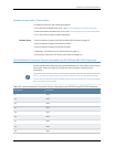

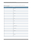
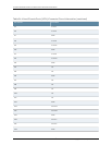

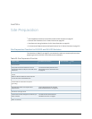

Table 23: Uplink Modules Connector Pinout Information for EX3200 and EX4200
Switches (continued)
Pin NamePin Number
GNDI11
GNDI12
GNDI13
GNDI14
GNDI15
Serial_TXI16
GNDI17
Uplink_P28_LED1I18
GNDI19
POWER(12V)I20
Related Topics Uplink Modules in EX3200 and EX4200 Switches on page 34•
• Front Panel of an EX3200 Switch on page 7
• Front Panel of an EX4200 Switch on page 9
• Installing an Uplink Module in an EX3200 or EX4200 Switch on page 135
• Removing an Uplink Module from an EX3200 or EX4200 Switch on page 177
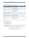
Virtual Chassis Ports Connector Pinout Information for EX4200 Switches
EX4200switchesusea68-pinconnectorcabletointerconnectswitchestoformaVirtual
Chassis. The cable is provided with the switch. Table 24 on page 81 provides the Virtual
Chassis ports (VCPs) connector pinout information.
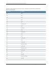
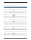
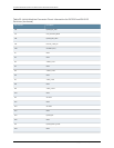
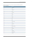
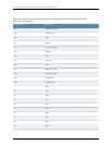
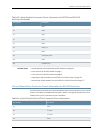
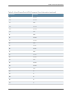
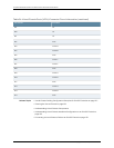
Table 24: Virtual Chassis Ports (VCPs) Connector Pinout Information
Pin NamePin Number
GNDA1
P1TXP0A2
P1TXN0A3
GNDA4
81Copyright©2010, JuniperNetworks, Inc.
Chapter3:ComponentSpecifications