


CHAPTER 2
Component Descriptions
•
LCD Panel in EX3200 and EX4200 Switches on page 13
•
Field-Replaceable Units in EX3200 and EX4200 Switches on page 18
•
Chassis Status LEDs in EX3200 Switches on page 19
•
Chassis Status LEDs in EX4200 Switches on page 20
•
Network Port LEDs in EX3200 and EX4200 Switches on page 21
•
Management Port LEDs in EX3200 and EX4200 Switches on page 25
•
Power Supply in EX3200 and EX4200 Switches on page 27
•
AC Power Supply LEDs in EX3200 and EX4200 Switches on page 30
•
DC Power Supply LEDs in EX3200 and EX4200 Switches on page 30
•
Cooling System and Airflow in an EX3200 Switch on page 31
•
Cooling System and Airflow in an EX4200 Switch on page 33
•
Uplink Modules in EX3200 and EX4200 Switches on page 34
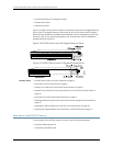
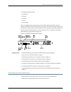
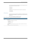
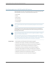
LCD Panel in EX3200 and EX4200 Switches
The LCD panel on the front panel of EX3200 and EX4200 switches shows two lines of
text, each a maximum of 16 characters in length. The LCD panel displays a variety of
informationabouttheswitchandalsoprovidesamenutoperformbasicoperationssuch
as initial setup and reboot.
There are two navigation buttons—Menu and Enter—to the right of the LCD panel.
See Figure 8 on page 13.
Figure 8: LCD Panel in EX3200 and EX4200 Switches
You can configure the second line of the LCD panel to display a custom message. If the
LCD panel is configured to display a custom message, the Menu button and the Enter
buttonaredisabled.SeeConfiguringtheLCDPanelonEXSeriesSwitches(CLIProcedure).
13Copyright©2010, JuniperNetworks, Inc.