


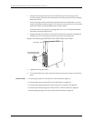
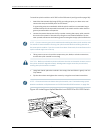
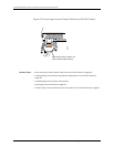

To install an uplink modulein an EX3200 or EX4200 switch(see Figure49on page136):
1. Attach the electrostatic discharge (ESD) grounding strap to your bare wrist, and
connect the strap to the ESD point on the chassis.
If a grounding strap is not available, hold the uplink module in its antistatic bag in
one hand and touch the exposed, bare metal of the switch with the other hand to
ground yourself and the component.
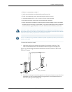
2. Loosen the screws that secure the flip-up door covering the empty uplink module
slot on the front panel of the switch by using the cross-head screwdriver, flip the
doorupward,and removethe blankingpanelcoveringthe emptyuplink moduleslot.
NOTE: Ifyouare removing anuplink moduleandinstallinganother uplink module,wait
for at least 10 seconds after removing the uplink module before installing the new or
thesame uplink module. If youdo notwait foratleast10 seconds,the interfacesonthe
uplink module might not come up.
3. Takingcare not to touch module components, pins, leads, or solder connections,
remove the uplink module from its bag.
CAUTION: Beforeyouslidetheuplinkmoduleintotheslotontheswitchchassis,ensure
the uplink module is aligned correctly. Misalignment might cause the pins to bend,
making the uplink module unusable.
4. Using both hands, place the module in the empty slot and slide it in gently until it is
fully seated.
5. Flip the door down and tighten the screws by using the cross-head screwdriver.
NOTE: If the switch does not detect the uplink module, see “Troubleshooting Uplink
ModuleInstallation or Replacement on EX3200 and EX4200 Switches” on page 194.
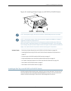
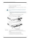
Figure 49: Installing an Uplink Module in an EX3200 or EX4200 Switch
Copyright ©2010,Juniper Networks,Inc.136
CompleteHardwareGuide forEX3200 andEX4200 EthernetSwitches