


Ensure that the wall onto which the switch is installed is stable and securely supported.
If you are mounting the switch in sheetrock (wall board with a gypsum plaster core) or
in wall board not backed by wall studs, use hollow wall anchors capable of supporting
the combined weight of two fully loaded chassis. Insert the screws into wall studs
wherever possible to provide added support for the chassis.
Use the wall-mount kit from Juniper Networks to mount the switch on a wall. The
wall-mount kit is not part of the standard package and needs to be ordered separately.
Related Topics Clearance Requirements for Airflow and Hardware Maintenance for EX3200 and
EX4200 Switches on page 96
•
• Wall-Mounting Warningfor EX3200 and EX4200 Switches on page 225
• Mounting an EX3200 or EX4200 Switch on a Desk or Other Level Surface on page 121
• Mounting an EX3200 or EX4200 Switch on a Wall on page 128
Clearance Requirements for Airflow and Hardware Maintenance for EX3200 and
EX4200 Switches
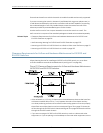
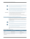
When planning the site for installing an EX3200 or EX4200 switch, you must allow
sufficient clearance around the installed switch (see Figure 27 on page 96).
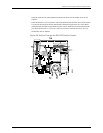
Figure27:ClearanceRequirementsforAirflowandHardwareMaintenance
for EX3200 and EX4200 Switches
•
Allow at least 6 in. (15.2 cm) of clearance on the side between devices that have fans
or blowers installed. Allow 2.8 in. (7 cm) between the side of the chassis and any
non-heat-producingsurfacesuchasawall.Forthecoolingsystemtofunctionproperly,
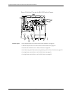
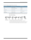
the airflow around the chassis must be unrestricted. Figure 28 on page 97 shows the
airflowthroughtheEX3200switchchassisandFigure29onpage98showstheairflow
through the EX4200 switch chassis.
•
If you are mounting an EX3200 or EX4200 switch on a rack or cabinet with other
equipment,orif youareplacingiton thedesktoporfloornearotherequipment, ensure
Copyright ©2010,Juniper Networks,Inc.96
CompleteHardwareGuide forEX3200 andEX4200 EthernetSwitches