


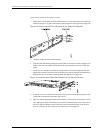
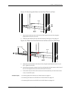
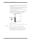
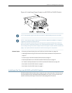
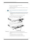
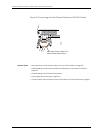

Figure 46: Installing a Power Supply in an EX3200 or EX4200 Switch
NOTE: Each power supplymust be connected toa dedicated powersource outlet.
NOTE: If you have a Juniper J-Care service contract, register any addition, change,or
upgradeof hardware components at
https://www.juniper.net/customers/csc/management/updateinstallbase.jsp. Failure to
do so can result in significant delays if you need replacement parts. This note applies
if you change the type of power supply or add a new type of uplink module. It does not
apply if you replace these components with the same type of component.
Related Topics Removing a Power Supply from an EX3200 or EX4200 Switch on page 174•
• Installing and Removing EX3200 and EX4200 Switch Hardware Components on
page 131
• Power Supply in EX3200 and EX4200 Switches on page 27
• Field-Replaceable Units in EX3200 and EX4200 Switches on page 18
• AC Power Cord Specifications for EX3200 and EX4200 Switches on page 102
• Rear Panel of an EX3200 Switch on page 8
• Rear Panel of an EX4200 Switch on page 11
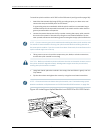
Installing a Fan Tray in an EX3200 or EX4200 Switch
EX3200 and EX4200 switches have a single fan tray on the rear panel. The fan tray is a
hot-removable and hot-insertable field-replaceable unit (FRU): Youcan remove and
replace it without powering off the switch or disrupting switch functions.
133Copyright©2010, JuniperNetworks, Inc.
Chapter10:Installing SwitchComponents