


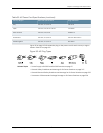


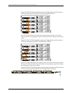
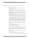


Figure 32: EX4200 Switches Mounted on a Single Rack and Connected
in a Ring Topology Using Short and Long Cables: Option 2
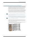
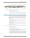
Figure 33 on page 108 shows five EX4200 switches stacked vertically in a rack and
interconnected in a ring topology using short-length and medium-length Virtual Chassis
cables.
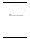
Figure 33: EX4200 Switches Mounted on a Single Rack and Connected
in a Ring Topology Using Short and Medium Cables
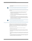
Figure34onpage108andFigure35onpage109showfiveEX4200switchesmountedon
thetoprowsofadjacentracksandinterconnectedinaringtopologyusingmedium-length
and long-length Virtual Chassis cables.
Figure34: EX4200 Switches Mountedon Adjacent Racks and Connected
in a Ring Topology Using Medium and Long Cables: Option 1
Copyright ©2010,Juniper Networks,Inc.108
CompleteHardwareGuide forEX3200 andEX4200 EthernetSwitches