


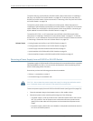
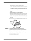
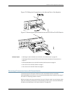
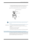

Figure 69: Removing a Fan Tray from an EX4200 Switch
NOTE: When a fan tray is removed,Fan/Blower is Absent is logged in the system log
and the system raises a minor alarm.
Related Topics Installing a Fan Tray in an EX3200 or EX4200 Switch on page 133•
• Installing and Removing EX3200 and EX4200 Switch Hardware Components on
page 131
• Cooling System and Airflow in an EX3200 Switch on page 31
• Cooling System and Airflow in an EX4200 Switch on page 33
• Field-Replaceable Units in EX3200 and EX4200 Switches on page 18
• Rear Panel of an EX3200 Switch on page 8
• Rear Panel of an EX4200 Switch on page 11
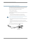
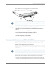
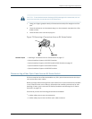
Removing an Uplink Module from an EX3200 or EX4200 Switch
IfyourEX3200 or EX4200switchincludesan optional uplinkmodule,it isinstalledinthe
switch's front panel. The different types of uplink modules are described in “Uplink
Modules in EX3200 and EX4200 Switches” on page 34.
TheuplinkmoduleinEX3200andEX4200switchesisahot-removableandhot-insertable
unit (FRU): Youcan remove and replace it without powering off the switch or disrupting
switch functions.
NOTE: If you have set an uplink moduleport asa Virtual Chassis port (VCP), removing
theuplinkmodulebreaksthesetting.YoumustresettheportasaVCPafteryoureplace
themodule.SeeSettinganUplinkModulePortasaVirtualChassisPort(CLIProcedure).
Before you begin removing an uplink module from an EX3200 or EX4200 switch:
•
Ensure that you have taken the necessary precautions to prevent ESD damage (see
“Prevention of Electrostatic Discharge Damage on EX Series Switches” on page 236).
177Copyright©2010,Juniper Networks,Inc.
Chapter13:RemovingSwitchComponents