


•
If there are any transceivers installed in the uplink module, remove them before you
remove the uplink module. For instructions on removing transceivers, see “Removing
a Transceiver from an EX Series Switch” on page 179.
Ensure that you have the following parts and tools available:
•
Electrostatic discharge (ESD) grounding strap (If a grounding strap is not available,
followthealternativegroundingmethoddescribedinStep1ofthefollowingprocedure.)
•
Cross-head screwdriver (provided in the uplink module kit)
•
An antistatic bag or antistatic mat
To remove an uplink module from an EX3200 or EX4200 switch:
1. Attach the electrostatic discharge (ESD) grounding strap to your bare wrist, and
connect the strap to the ESD point on the chassis.
If a grounding strap is not available, touch the exposed, bare metal of the switch
with the other hand to ground yourself and the component.
2. Loosen the screws that secure the flip-up door covering the uplink module slot on
the front panel of the switch by using the cross-head screwdriver provided with the
uplink module kit and flip the door upward.
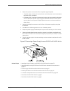
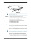
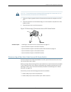
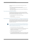
3. Insert the ball end of the screwdriver in the keyhole on the front panel of the uplink
module and slide the screwdriver to the narrow part of the keyhole (see Figure 70
on page 179).
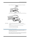
CAUTION: Ensure the screwdriver does not slip out of the keyhole when youpull the
uplink module out of the switch chassis.
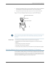
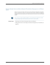
4. Using both hands, gently pull the screwdriverto slide the uplink modulehalfway out
of the chassis (see Figure 71 on page 179).
5. Place one hand under the uplink module to support it and slide it completely out of
the chassis.
6. Slide the screwdriver out of the keyhole.
7. Place the uplink module in an antistatic bag or on an antistatic mat placed on a flat,
stable surface.
Copyright ©2010,Juniper Networks,Inc.178
CompleteHardwareGuide forEX3200 andEX4200 EthernetSwitches