


• Connecting a Fiber-Optic Cable to an EX Series Switch on page 158
• Optical Interface Support in EX2200 Switches
• Optical Interface Support in EX3200 and EX4200 Switches on page 43
• Optical Interface Support in EX4500 Switches
• Optical Interface Support in EX8200 Switches
Connecting a Virtual Chassis Cable to an EX4200 Switch
EX4200switcheshavetwoVirtualChassisportsontherearpanel.YoucanusetheVirtual
Chassis ports to interconnect up to 10 EX4200 switches, enabling them to operate as a
unified singlehigh bandwidth switch. To see illustrations of a few VirtualChassis cabling
configurationexamples,see“VirtualChassisCablingConfigurationExamplesforEX4200
Switches” on page 107.
Ensure that you have the following parts and tools available:
•
A cross-head screwdriver (provided in the uplink module kit)
NOTE: If youorderVirtualChassiscablesseparately,youmust reusethe lockingcovers
provided with the original cableor order Virtual Chassis cable locking coversalso
separately.
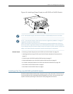
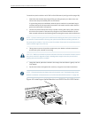
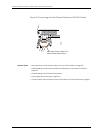
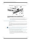
To connect a Virtual Chassis cable to an EX4200 switch (see Figure 51 on page 140):
1. Taking care not to touch module components, pins, leads, or solder connections,
remove the Virtual Chassis cable from its bag.
2. Using both hands, place the Virtual Chassis cable connector in the empty Virtual
Chassis port and slide it in gently until it is fully seated.
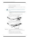
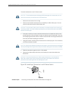
3. Slidethe locking cover over the Virtual Chassis cable connector.
4. Tighten the screws on the locking cover by using the cross-head screwdriver.
139Copyright©2010,Juniper Networks, Inc.
Chapter10:Installing SwitchComponents