


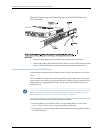
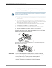

7. Close the input circuit breaker.
8. Verifythat the LEDs on the power supply are lit green and are on steadily.
Related Topics Connecting and Configuring an EX Series Switch (CLI Procedure) on page 165•
• Connecting and Configuring an EX Series Switch (J-Web Procedure) on page 167
• Power Supply in EX3200 and EX4200 Switches on page 27
• DC Power Supply LEDs in EX3200 and EX4200 Switches on page 30
Connecting an EX Series Switch to a Network for Out-of-Band Management
YoucanmonitorandmanageanEXSeriesswitchusingadedicatedmanagementchannel.
EX Series switches have a management port with an RJ-45 connector for out-of-band
management. Use the management port to connect the EX Series switch to the
management device.
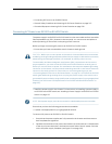
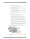
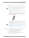
Ensure that you have an Ethernet cable with an RJ-45 connector available. One such
cable is provided with the switch. Figure 59 on page 152 shows the RJ-45 connector of
the Ethernet cable supplied with the switch.
Figure 59: Ethernet Cable Connector
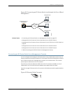
To connect an EX Series switch to a network for out-of-band management (see Figure
60 on page 153):
1. Connect one end of the Ethernet cable to the management port (labeled MGMT)
on the EX Series switch.
For the location of the MGMT port on different EX Series switches:
•
See Rear Panel of an EX2200 Switch.
•
See “Rear Panel of an EX3200 Switch” on page 8.
•
See “Rear Panel of an EX4200 Switch” on page 11.
•
See Front Panel of an EX4500 Switch.
•
See Switch Fabric and Routing Engine (SRE) Module in an EX8208 Switch.
•
See Routing Engine (RE) Module in an EX8216 Switch.
2. Connect the other end of the Ethernet cable to the management device.
Copyright ©2010,Juniper Networks,Inc.152
CompleteHardwareGuide forEX3200 andEX4200 EthernetSwitches