


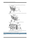
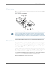
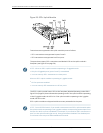


Figure 25: SFP+ Uplink Module
Transceivers are supported in the uplink module’s ports as follows:
•
SFP+ transceivers are supported in ports 0 and 2.
•
SFP transceivers are supported in all four ports.
The ports that support SFP+ transceivers are labeled 10 G on the uplink module’s
faceplate (see Figure 25 on page 36).
NOTE: When an SFP+ uplink module is operating in 10-gigabit mode:
•
Only the 10-gigabit ports (ports 0 and 2) are enabled.
•
You can use only SFP+ transceivers in those ports.
When an SFP+ uplink module is operating in 1-gigabit mode:
•
All four ports are enabled.
•
You can use only SFP transceivers in all four ports.
The SFP+ uplink module has an LED on the faceplate (labeled Operating mode LED in
Figure25onpage36)thatindicatestheoperatingmode.Iftheuplinkmoduleisoperating
in the 10-gigabit mode, the LED is lit. If the uplink module is operating in the 1-gigabit
mode, the LED is unlit.
SFP+ uplink modules are shipped with dust covers preinstalled in the ports.
NOTE: OnanEX3200switch,ifyouinstallatransceiverinanSFP+uplinkmodulewhen
theuplinkmoduleisoperatinginthe1-gigabitmode,acorrespondingnetworkportfrom
the lastfour built-in ports is disabled. For example, if you install an SFP+ transceiverin
port 2 on the uplink module (ge-0/1/3), then ge-0/0/23is disabled. The disabled port
is not listedin the output of showinterface commands.
Copyright ©2010,Juniper Networks,Inc.36
CompleteHardwareGuide forEX3200 andEX4200 EthernetSwitches