


•
Phillips (+) screwdriver, number 2
•
2 wall-mount brackets (provided with the wall-mount kit)
•
12 wall-mount bracket screws (provided with the wall-mount kit)
•
4 mounting screws (8-32 x 1.25 in. or M4 x 30 mm) (not included)
•
Dust covers for ports (for EX4200-24F switches only; optional)
•
Hollow wall anchors capable of supporting the combined weight of two fully loaded
switches,upto44lb(20kg)(notincluded)—ifyouaremountingtheswitchinsheetrock
(wall board with a gypsum plaster core) or in wall board not backed by wall studs
WARNING: When mounted in a vertical position, an EX3200 or EX4200 switch must
be oriented with the front panel of the chassis pointing down in order to ensure proper
airflow and meet safety requirementsin the event of a fire.
NOTE: For easier lifting, install any additional powersupplies only after you mount the
switch on the wall.
To mount the switch on a wall:
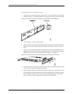
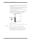
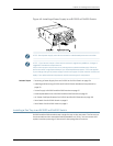
1. Attach the wall-mount brackets to the sides of the chassis using four of the
wall-mount bracket screws on each side, as shown in Figure 44 on page 129.
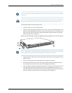
Figure 44: Attaching Wall-Mount Brackets to an EX3200 or EX4200
Switch Chassis
g020200
Front panel
Rear panel
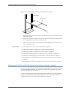
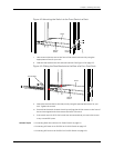
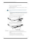
2. If you are mounting two switches together,line the second switch on top of the first
and attach it to the mounting brackets using two wall-mount bracket screws on
each side (see Figure 45 on page 130).
129Copyright©2010,Juniper Networks, Inc.
Chapter9:Installing theSwitch