


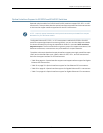

•
If the switch is running Junos OS Release 9.5 or earlier,the formatting method must
usea masterboot record. Windows formatting,bydefault, doesnot use a master boot
record. See the documentation for your USB flash drive for information on how your
USB flash drive is formatted.
Related Topics See Rear Panel of an EX2200 Switch for port location.•
• See Rear Panel of an EX3200 Switch on page 8 for port location.
• See Rear Panel of an EX4200 Switch on page 11 for port location.
• See Front Panel of an EX4500 Switch for port location.
• See Switch Fabric and Routing Engine (SRE) Module in an EX8208 Switch for port
location.
• See Routing Engine (RE) Module in an EX8216 Switch for port location.
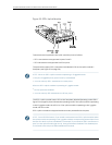
• Booting an EX Series Switch Using a Software Package Stored on a USB Flash Drive
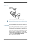
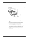
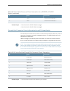
Network Port Connector Pinout Information for an EX3200 or EX4200 Switch
A network port on an EX3200 or EX4200 switch uses an RJ-45 connector to connect to
a device.
The port uses an autosensing RJ-45 connector to support a 10/100/1000Base-T
connection. Two LEDs on the port indicate link/activity on the port and the port status.
See “Network Port LEDs in EX3200 and EX4200 Switches” on page 21.
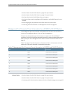
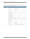
Table 15 on page 40 provides the pinout information for the RJ-45 connector. An RJ-45
cable, with a connector attached, is supplied with the switch.
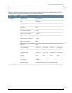
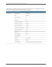
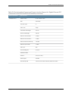
Table 15: Network Port Connector Pinout Information for an EX3200 or EX4200 Switch
DescriptionSignalPin
Transmit/receive datapair 1
NegativeVport(in PoEmodels)
TRP1+1
Transmit/receive datapair 1
NegativeVport(in PoEmodels)
TRP1-2
Transmit/receive datapair 2
Positive Vport (in PoEmodels)
TRP2+3
Transmit/receive datapair 3TRP3+4
Transmit/receive datapair 3TRP3-5
Transmit/receive datapair 2
Positive Vport (in PoEmodels)
TRP2-6
Copyright ©2010,Juniper Networks,Inc.40
CompleteHardwareGuide forEX3200 andEX4200 EthernetSwitches