


• Connecting DC Power to an EX8200 Switch
• General Safety Guidelines and Warnings for EX Series Switches on page 207
• Grounded Equipment Warning for EX Series Switches on page 226
Connecting AC Power to an EX3200 or EX4200 Switch
ThepowersupplyinanEX3200 orEX4200switchisahot-removableandhot-insertable
field-replaceable unit (FRU) located on the rear panel: Youcan remove and replace it
without powering off the switch or disrupting switch functions.
Before you begin connecting AC power to an EX3200 or EX4200 switch:
•
Ensure that you have connected the switch chassis to earth ground.
CAUTION: Before you connect power to the switch, a licensed electrician must attach
acablelugtothegroundingandpowercablesthatyousupply.Acablewithanincorrectly
attached lug can damage the switch (for example, by causing a short circuit).
To meet safety and electromagnetic interference (EMI) requirements and to ensure
proper operation, you must connect EX3200 and EX4200 switches to earth ground
before you connect them to power. For installations that require a separate grounding
conductor to the chassis, use the protective earthing terminal on the switch chassis to
connect tothe earth ground. For instructions on connecting earth ground, see
“Connecting Earth Ground to an EX Series Switch” on page141. An EX3200 or EX4200
switch gets additional grounding when you plug the power supply in the switch into a
groundedACpoweroutletbyusingtheACpowercordappropriateforyourgeographical
location (see “AC Power Cord Specifications for EX3200 and EX4200 Switches” on
page 102).
•
Install the power supply in the chassis. For instructions on installing a power supply in
anEX3200 or EX4200switch,see“Installinga PowerSupply inan EX3200 orEX4200
Switch” on page 132.
NOTE: Each power supplymust be connected toa dedicated powersource outlet.
Ensure that you have the following parts and tools available:
•
A power cord appropriate for your geographical location
To connect AC power to an EX3200 or EX4200 switch:
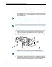
1. Ensure that the power supplies are fully inserted in the chassis and the screws on
their faceplates are tightened.
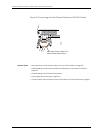
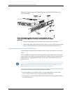
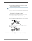
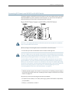
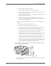
2. Squeeze the two sides of the power cord retainer clip and insert the L-shaped ends
of the wire clip into the holes in the bracket on each side of the AC power cord inlet
on the AC power supply faceplate (see Figure 54 on page 148).
147Copyright© 2010,Juniper Networks,Inc.
Chapter11:Connectingthe Switch