


To connect DC power to an EX3200 or EX4200 switch:
1. Ensure that the power supplies are fully inserted in the chassis and the screws on
their faceplates are tightened.
2. Ensure thatthe input circuitbreakeris open so thatthe voltageacrossthe DC power
source cable leads is 0 V and that the cable leads will not become active while you
are connecting DC power.
NOTE: TheDCpowersupplyinEX3200andEX4200switcheshasfourterminalslabeled
A+, B+, A–, and B– (see Figure56 on page149) forconnectingDC powersourcecables
labeled positive(+) and negative(–). The DC powersupplies for EX3200 and EX4200
switchesareshippedwith jumpersfromA+inputtoB+ inputtiedtogetherand jumpers
from A– input to B– input tied together.
NOTE: The A+ and B+ terminals are referred to as +RTN and A– and B– terminals are
referred to as –48 V in “DC Power Wiring Sequence Warning for EX Series Switches”
on page 244 and “DC Power Electrical Safety Guidelines for EX Series Switches” on
page 240.
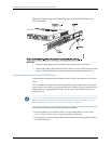
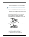
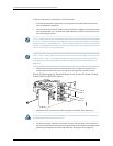
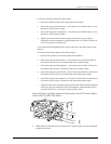
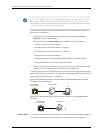
3. Remove the screw securing the terminal block cover using the screwdriver and
remove the terminal block cover (see Figure 57 on page 150). Save the screw.
Figure 57: Removing the Terminal Block Cover from a DC Power Supply
in an EX3200 or EX4200 Switch
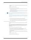
4. Remove the screws on the terminals using the screwdriver. Save the screws.
WARNING: Ensure that the power cables do not block access to switch components
or drape where people can trip on them.
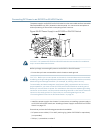
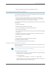
5. Connect the power supplies to the power sources. Secure power source cables to
thepowersuppliesbyscrewingtheringlugsattachedtothecablestotheappropriate
terminals by using the screw from the terminals (see Figure 58 on page 151).
Copyright ©2010,Juniper Networks,Inc.150
CompleteHardwareGuide forEX3200 andEX4200 EthernetSwitches