


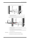

• Rear Panel of an EX3200 Switch on page 8
• Rear Panel of an EX4200 Switch on page 11
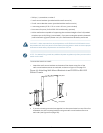
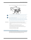
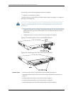
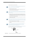
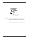
Installing an Uplink Module in an EX3200 or EX4200 Switch
If yourEX3200 or EX4200switchincludes an optional uplink module,you installit inthe
switch's front panel. The different types of uplink modules are described in “Uplink
Modules in EX3200 and EX4200 Switches” on page 34.
TheuplinkmoduleinEX3200andEX4200switchesisahot-removableandhot-insertable
unit (FRU): Youcan remove and replace it without powering off the switch or disrupting
switch functions.
NOTE: If you have set an uplink moduleport asa Virtual Chassis port (VCP), removing
theuplinkmodulebreaksthesetting.YoumustresettheportasaVCPafteryoureplace
themodule.SeeSettinganUplinkModulePortasaVirtualChassisPort(CLIProcedure).
NOTE: On an EX3200 switch, if you install a transceiver in an SFP uplink module or in
anSFP+uplinkmodulewhentheSFP+uplinkmoduleisoperatinginthe1-gigabitmode,
a corresponding network port from the last fourbuilt-in ports is disabled. For example,
ifyou installan SFP or SFP+transceiver inport 2 on the uplink module(ge-0/1/3), then
ge-0/0/23is disabled. The disabled port is not listed in the output of showinterface
commands.
When an SFP+ uplink module is operating in 10-gigabit mode:
•
Only the 10-gigabit ports (ports 0 and 2) are enabled.
•
You can use only SFP+ transceivers in those ports.
When an SFP+ uplink module is operating in 1-gigabit mode:
•
All four ports are enabled.
•
You can use only SFP transceivers in all four ports.
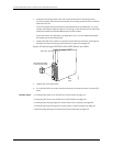
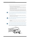
Before you begin installing an uplink module in an EX3200 or EX4200 switch:
•
Ensure that you have taken the necessary precautions to prevent ESD damage (see
“Prevention of Electrostatic Discharge Damage on EX Series Switches” on page 236).
Ensure that you have the following parts and tools available:
•
Electrostatic discharge (ESD) grounding strap (If a grounding strap is not available,
followthealternativegroundingmethoddescribedinStep1ofthefollowingprocedure.)
•
Cross-head screwdriver (provided in the uplink module kit)
135Copyright©2010, JuniperNetworks, Inc.
Chapter10:Installing SwitchComponents