


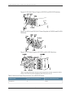
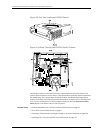

Power Supply in EX3200 and EX4200 Switches
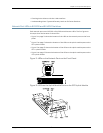
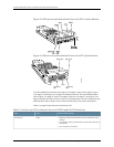
The power supply in EX3200 and EX4200 switches (see Figure 17 on page 28, Figure 18
on page 28 and Figure 19 on page 28) is a hot-removable and hot-insertable
field-replaceable unit (FRU) that you can install on the rear panel without powering off
the switch or disrupting the switching function. EX4200 switches have an internal
redundant power supply, making the power supply in EX4200 switches fully redundant.
The power supply in EX3200 switches is not redundant.
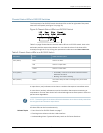
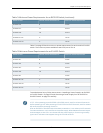
EX3200 and EX4200 switches use powerthat provides two DC output voltages: 12 V for
system and logic power and 48–51 V (or higher, to compensate for voltage drops along
the path from the power supplies to the RJ-45 connector) for PoE ports.
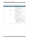
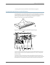
The AC power supply in EX3200 and EX4200 switches is available in 320 W, 600 W,
and 930 W models. The exterior of the 600 W model is identical to that of the 930 W
model. The 320 W power supply is flush with the chassis. The 600 W power supply and
930 W power supply extend out of the chassis by 2.25 in. The power cord retainer clips
extend out of the power supply by 3 in. The number of ports on which PoE is enabled
determines the minimum power requirements.
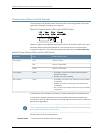
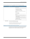
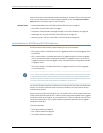
The DC power supply in EX3200 and EX4200 switches is available in a 190 W model,
with dual input feeds for power resiliency. Youcan install redundant DC power supplies
in an EX4200 switch to achieve both power supply and power feed resiliency.
NOTE: TheDC power supply inEX3200 and EX4200switchesdoesnot supportPower
overEthernet(PoE);youcanuseeitheranexternalpowerinjectororanACpowersupply
to supplypower to PoE devicesthat you connect to the switch.
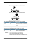
NOTE: TheDCpowersupplyinEX3200andEX4200switcheshasfourterminalslabeled
A+, B+, A–,and B– (see Figure 19 on page 28) for connecting DC power source cables
labeled positive(+) and negative(–). The DC powersupplies for EX3200 and EX4200
switchesareshippedwith jumpersfromA+inputtoB+ inputtiedtogetherand jumpers
from A– input to B– input tied together.
NOTE: The A+ and B+ terminals are referred to as +RTN and A– and B– terminals are
referred to as –48 V in “DC Power Wiring Sequence Warning for EX Series Switches”
on page 244 and “DC Power Electrical Safety Guidelines for EX Series Switches” on
page 240.
27Copyright©2010,Juniper Networks,Inc.
Chapter2:ComponentDescriptions