


Virtual Chassis Cabling Configuration Examples for EX4200 Switches
You can install EX4200 switches in a single rack or multiple racks, or in different wiring
closets,andinterconnectthemtoformaVirtualChassis.Thereare two dedicatedVirtual
Chassis ports (VCPs) on the rear panel of the EX4200 switch that are used exclusively
to interconnect EX4200 switches as a Virtual Chassis. The physical location of the
switches in a Virtual Chassis is restricted only by the maximum length supported for
cablestoconnecttheVCPs.Themaximumcablelengthforinterconnectingthededicated
VCPs is 5 meters. If you want to interconnect EX4200 switches that are located beyond
the reach of the dedicated VCP cables, you can install the XFP uplink module, the SFP
uplink module, or the SFP+ uplink module and set the uplink module ports as VCP
interfaces. See Setting an Uplink Module Port as a Virtual Chassis Port (CLI Procedure).
NOTE: The interfacesfor the two dedicated VCPs are operational by default. However,
if you are using the uplink module ports as VCPs, you must explicitly set the uplink
moduleports to function as VCPs.
ThefollowingillustrationsdescribevariousVirtualChassiscablingconfigurationexamples.
NOTE: For increased availability and redundancy, we recommend that you always
configure your Virtual Chassis in a ring topology.
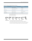
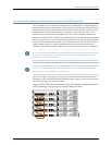
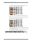
Figure 31 on page 107 and Figure 32 on page 108 show five EX4200 switches stacked
vertically in a rack and interconnected in a ring topology using four short Virtual Chassis
cables and one long Virtual Chassis cable.
Figure 31: EX4200 Switches Mounted on a Single Rack and Connected in
a Ring Topology Using Short and Long Cables: Option 1
107Copyright ©2010,Juniper Networks,Inc.
Chapter8:Planningthe VirtualChassis