


To mount the switch on four posts in a rack:
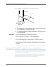
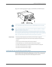
1. Attachthefrontbrackets(eithertheflushorthe2-in.-recessbrackets)totheside-rail
bracketsusingsix4-40flat-headPhillipsmountingscrews.SeeFigure40onpage126.
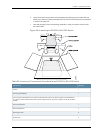
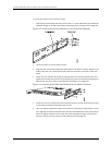
Figure 40: Attaching the Front Bracket to the Side-Rail Bracket
2. Place the switch on a flat, stable surface.
3. Alignthe side-railbracketsalongthe sidepanels of theswitchchassis.Align thetwo
holes in the rear of the side-rail brackets with the two holes on the rear of the side
panel.
4. Insert 4x6-mm Phillips flat-head mounting screws into the two aligned holes and
tighten the screws. Ensure thatthe remaining four holes in the side-rail brackets are
aligned with the four holes in the side panel. See Figure 41 on page 126.
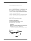
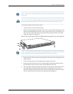
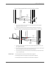
Figure 41: Attaching the Side-Rail Bracket to the Switch Chassis
5. Insert the 4x6-mm Phillips flat-headmounting screwsinto the remaining fourholes
in the side-rail brackets and tighten the screws.
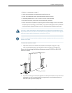
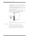
6. Have one persongrasp both sides of the switch, lift the switch, and position it in the
rack, aligning the side-rail bracket holes with the threaded holes in the front post of
the rack. Align the bottom hole in both the mounting brackets with a hole in each
rack rail, making sure the chassis is level. See Figure 42 on page 127.
Copyright ©2010,Juniper Networks,Inc.126
CompleteHardwareGuide forEX3200 andEX4200 EthernetSwitches