


CHAPTER 10
Installing Switch Components
•
Installing and Removing EX3200 and EX4200 Switch Hardware
Components on page 131
•
Installing a Power Supply in an EX3200 or EX4200 Switch on page 132
•
Installing a Fan Tray in an EX3200 or EX4200 Switch on page 133
•
Installing an Uplink Module in an EX3200 or EX4200 Switch on page 135
•
Installing a Transceiver in an EX Series Switch on page 137
•
Connecting a Virtual Chassis Cable to an EX4200 Switch on page 139
Installing and Removing EX3200 and EX4200 Switch Hardware Components
TheEX3200 and EX4200 switchchassisis a rigid sheet-metalstructurethathouses the
hardware components. The field-replaceable units (FRUs) in EX3200 and EX4200
switches are:
•
Power supply
•
Fan tray
•
Uplink module
•
SFP transceiver
•
SFP+ transceiver
•
XFP transceiver
The power supply, fan tray, uplink module, and transceivers are hot-removable and
hot-insertable: You can remove and replace them without powering off the switch or
disrupting switch functions.
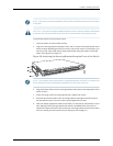
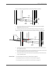
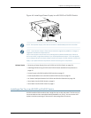
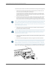
ToinstallapowersupplyinanEX3200orEX4200switch,followinstructionsin“Installing
aPowerSupplyinan EX3200or EX4200Switch”on page132.To removea power supply
from an EX3200 or EX4200 switch, follow instructions in “Removing a Power Supply
from an EX3200 or EX4200 Switch” on page 174.
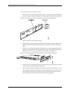
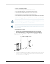
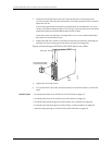
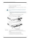
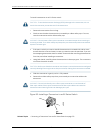
To install a fan tray in an EX3200 or EX4200 switch, follow instructions in “Installing a
Fan Tray in an EX3200 or EX4200 Switch” on page 133. To remove a fan tray from an
EX3200 or EX4200 switch, follow instructions in “Removing a Fan Tray froman EX3200
or EX4200 Switch” on page 176.
131Copyright©2010, JuniperNetworks, Inc.