


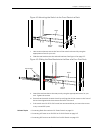
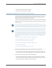

3. Insert the mounting screws in the wall. Insert the top pair of mounting screws
474.35 mm apart, and insert the second pair of mounting screws 151.81 mm directly
below the first set.
If the mounting screws are inserted in wall board with no stud behind it, you must
use dry wall anchors ratedto support 75 lb (34 kg). Insert the screwsinto wall studs
wherever possible to provide added support for the chassis.
Screw the screws only part way in, leaving about 1/4in. (6 mm) distance between
the head of the screw and the wall.
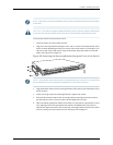
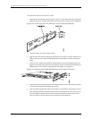
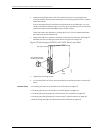
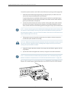
4. Grasp each side of the switch or switches, lift the switch or switches, and hang the
brackets from the mounting screws as shown in Figure 45 on page 130.
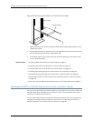
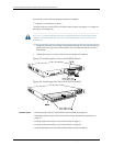
Figure 45: Mounting an EX3200 or EX4200 Switch on a Wall
Hang attached brackets
on wall-mounted screws.
g020201
Front
panel
Rear panel
5. Tighten the mounting screws.
6. If it is an EX4200-24F switch, we recommend you insert dust covers in unused SFP
ports.
Related Topics • Connecting AC Power to an EX3200 or EX4200 Switch on page 147
• Connecting DC Power to an EX3200 or EX4200 Switch on page 149
• Connecting and Configuring an EX Series Switch (CLI Procedure) on page 165
• Connecting and Configuring an EX Series Switch (J-Web Procedure) on page 167
• Wall-Mounting Warningfor EX3200 and EX4200 Switches on page 225
Copyright ©2010,Juniper Networks,Inc.130
CompleteHardwareGuide forEX3200 andEX4200 EthernetSwitches