


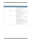
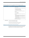
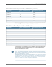
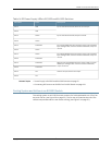


Table 14: DC Power Supply LEDs in EX3200 and EX4200 Switches
DescriptionColorLED Label
InputsA and B are normal, but there is no output.RedLED A
RedLED B
InputsA and B are normal; output is normal.GreenLED A
GreenLED B
Input A hasfailed becausethe powersupplyfuse hasfailed,
input voltage is low,or thereis a looseconnection;output is
normal.
Flash RedLED A
GreenLED B
Input B hasfailed becausethe powersupplyfuse hasfailed,
input voltage is low,or thereis a looseconnection;output is
normal.
GreenLED A
Flash RedLED B
Both inputshavefailed becausethe powersupplyfuse has
failed,input voltageis low, or thereis a looseconnection;
output is normal.
Flash RedLED A
Flash RedLED B
There is no input; there is no output.OffLEDA
OffLEDB
Related Topics Power Supply in EX3200 and EX4200 Switches on page 27•
• Connecting DC Power to an EX3200 or EX4200 Switch on page 149
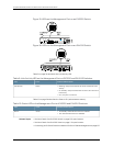
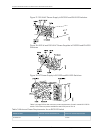
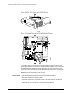
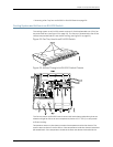
Cooling System and Airflow in an EX3200 Switch
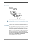
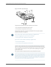
The cooling system in an EX3200 switch consists of a field-replaceable unit (FRU) fan
tray with one fan (see Figure 20 on page 32). The fan tray is located at the rear of the
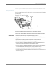
chassis and provides side-to-rear chassis cooling (see Figure 21 on page 32).
31Copyright©2010, JuniperNetworks, Inc.
Chapter2:ComponentDescriptions