


magicolor 330 - Base Engine Service Manual 2-3
Fault Isolation Procedures
General Notes on Using FIPs
1. FIPs assume there is no malfunction in the printer Controller (ESS). If you are unable to fix a problem using the
FIPS, we recommend that you replace the printer Controller.
2. FIPs frequently use new or "known good" components as troubleshooting tools. We recommend you carry a
spare Fuser Assembly, MCU PWB, Controller PWB, LVPS, and Xerographic Cartridge.
3. Unless indicated otherwise, the instruction "switch ON printer main power" means for you to switch ON printer
power and let the printer proceed through power-on diagnostics and warm-up until it is on-line and ready to print.
4. Conventions used to represent connectors:
P/J XX means a Plug and its corresponding Jack are connected.
PXX means a Plug is disconnected. (Unless this plug is soldered to a PWB).
JXX means a Jack is disconnected. (Unless this jack is soldered to a PWB).
5. When you are instructed to take a voltage reading between "P/J A–B and P/J X–Y", place the red probe (+) of
your meter on pin B of P/J A, and place the black probe (–) of your meter on pin Y of P/J X.
6. When you are instructed to take voltage readings between "P/J X and P/J Y" (without specified pin numbers),
check all voltage carrying pins. Refer to the Wiring Diagrams for signals and pin numbers.
7. When you are instructed to take a voltage reading, the black probe (–) is generally connected to a pin that is
either RTN (Return) or SG (Signal Ground). You can substitute any RTN pin or test point in the printer, and you
can use FG (Frame Ground) in place of any SG pin or test point.
8. Unless a FIP instructs you otherwise; before measuring voltages make sure the printer is switched ON, the Xero-
graphic Cartridge and the Paper Cassettes are installed, and all of the interlock switches are actuated.
9. All voltage values given in the FIPs are approximate values. Actual measured voltages may vary more
than 25% from the values stated in the FIPs. The main purpose of most voltage readings taken in the FIPs
is to determine whether or not a component is receiving the correct HIGH voltage value from the power
supply and if gating (a voltage drop) occurs during component actuation. Gating signals may be nothing
more than a pulse, resulting in a momentary drop in voltage that may be difficult or impossible to read on
the average multimeter.
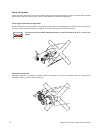
10. FIPs may instruct you to remove or replace a component. Refer to Section 9 Removal and Replacement Proce-
dures for information on how to remove and reinstall a component.
11. When a FIP instructs you to replace a component, and that component is part of a larger assembly,
you should replace the entire assembly.