magicolor 330 - Base Engine Service Manual 9-5
Removal and Replacement Procedures
Removal and Replacement Procedures (RRPs)
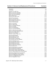
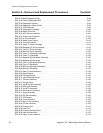
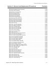
This section contains the removal and replacement procedures for major parts within the printer.
Preparation
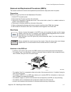
Before you begin any Removal and Replacement Procedure:
1. Switch OFF the printer power.
2. Disconnect the AC power cord from the wall outlet.
3. Remove the Xerographic Cartridge and cover it with a dark cloth or place it in a sealed container to
protect it from exposure to light.
4. Disconnect all interface cables from the back of the printer.
5. Wear an electrostatic discharge wrist strap to protect sensitive printer PWBs from damage.
6. Wait at least 45 minutes for the Fuser to cool before removing parts in the Fuser area.
Work Notes
Names of parts that appear in the RRPs may not be exactly the same as the names
appear in the Parts List. For example, a part called the Metal Registration Roll in an RRP
may appear on the Parts List as Registration Metal Roll.
When working on an RRP ignore any noted prerequisite steps if you have already per-
formed them.
Always reinstall the correct type and size screws. Using the wrong screw can damage
tapped holes. Do not use excessive force to either remove or install a part.
Notations in the RRP text
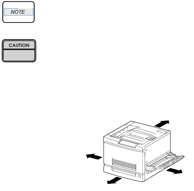
• Locations, such as R or right, given in the RRPs assume you are facing the printer console panel.
• The notation "rear" of a component, in place or removed, refers to the side of the component that is,
when installed, facing the rear of the print engine.
• The notation "front" of a component refers to the side of the component that is, if installed, facing the
front of the print engine.
• The notation “(RRP X.Y)” in a RRP step, directs you to another RRP for information on how to per-
form a related or pre-requisite procedure.
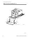
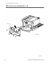
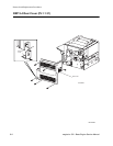
• The notation “(Figure x)” points to the illustration that corresponds to the RRP you are performing.
• The notation “(PLX)” indicates that this component is listed in the PLX parts list.
• Arrows in an illustration show direction of movement when removing a component.
RS1000XB
Rear
Front
Right
Left
RS1000XB


