


magicolor 330 - Base Engine Service Manual 9-207
Removal and Replacement Procedures
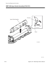
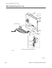
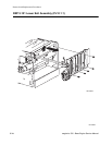
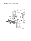
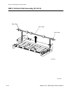
RRP 9.101 Lower Exit Assembly (PL10.1.1)
Removal
1. Remove the Upper Exit Assembly (RRP 9.102).
2. Disconnect P/J 161 from the P/J the near the top rear of the Lower Exit Assembly.
3. Disconnect P/J 111 from the P/J near the top rear of the Lower Exit Assembly.
4. Remove the five screws securing the Lower Exit Assembly to the printer frame.
5. Lift the Lower Exit Assembly to unhook the top of the Assembly from the printer frame and remove the
Assembly.
6. Disconnect P/J 165 from the Top Exit Senor and P/J 166 from the Exit Chute Switch, both located on
the back of the Lower Exit Assembly.
7. Remove the wires from the wire clips that are molded into the side of the Lower Exit Assembly.
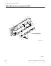
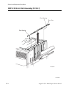
Replacement
1. Reconnect P/J 165 to the Top Exit Senor and P/J 166 to the Exit Chute Switch.
2. Route the wire harnesses through the groove in the top rear of the Lower Exit Assembly.
3. Hook the top of the Lower Exit Assembly onto the top of the printer frame and position the Assembly
so the five screw holes in the Assembly line up with the five screw holes in the printer frame.
4. Use five screws to secure the Lower Exit Assembly to the printer frame.
5. Reconnect P/J 111 to the P/J near the top rear of the Lower Exit Assembly.
6. Reconnect P/J 161 to the P/J near the top rear of the Lower Exit Assembly.
7. Reinstall the wires under the wire clips that are molded into the side of the Lower Exit Assembly.
8. Reinstall the Upper Exit Assembly (RRP 9.102).