


magicolor 330 - Base Engine Service Manual 9-73
Removal and Replacement Procedures
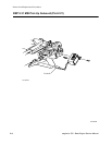
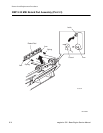
RRP 9.34 MSI Bottom Assembly (PL4.3.9)
Removal
1. Remove the MSI Top Cover (RRP 9.26).
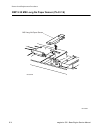
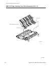
2. Remove the Pick Up Spring from the Clutch Bracket.
3. Remove the E ring securing the Pick Up Shaft to the Front MSI Bearing.
4. Remove the E ring securing the Pick Up Shaft to the Rear MSI Bearing and remove the Shaft.
5. Carefully pry the rear pivot arm of the MSI Bottom Assembly out of the pivot hole in the MSI Frame.
6. Slide the front pivot arm of the MSI Bottom Assembly out of the pivot hole in the MSI Frame and
remove the MSI Bottom Assembly.
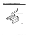
7. If installed, remove the screw securing the ground wire to the Bottom Assembly and remove the wire.
8. Disconnect the P/Js from the two sensors that are attached to the bottom of the MSI Bottom Assembly.
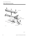
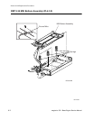
Replacement
1. Reconnect the two P/Js to the two sensors that are attached to the bottom of the MSI Bottom Assem-
bly.
2. If installed, reinstall the ground wire to the Bottom Assembly and use one screw to secure the wire.
3. Position the MSI Bottom Assembly on top of the MSI Frame.
4. Slide the front pivot arm of the MSI Bottom Assembly into the pivot hole in the MSI Frame.
5. Pull back on the rear pivot arm of the MSI Bottom Assembly and slide the rear pivot arm into the pivot
hole in the MSI Frame.
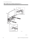
6. Once the MSI Bottom Assembly is secured in place, lift the Assembly and reinstall the three MSI
Springs.
7. Push the Retard Pad out of the way and then press and release the MSI Bottom Assembly to make
sure the Springs are in place and provide the Assembly with a strong spring return.
8. Push the Pick Up Solenoid arm down and out of the way while you reinstall the Pick Up Shaft into the
notches in the MSI Frame.
9. Slide the Front MSI Bearing and the Rear MSI Bearing into the notches and use an E ring to secure
each end of the Shaft to the bearings.
10. Reconnect the Pick Up Spring to the Clutch Bracket.
11. Reinstall the MSI Top Cover (RRP 9.26).