magicolor 330 - Base Engine Service Manual 9-11
Removal and Replacement Procedures
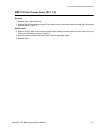
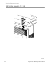
RRP 9.3 Top Cover Assembly (PL1.1.20)
Removal
1. Remove the Rear Cover (RRP 9.4).
2. Open the Front Cover.
3. Remove the two screws securing the Top Cover to the front of the printer frame.
4. Open the Upper Exit Cover.
5. Lift the rear of the Top Cover off of the rear of the printer frame.
6. Reach under the Top Cover and disconnect P/J317 from the Operation Panel.
7. Slide the Top Cover to the front of the printer and lift the front of the Cover off of the printer frame.
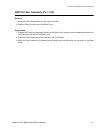
Replacement
1. Remove the Rear Cover (RRP 9.4).
2. Open the Front Cover.
3. Open the Upper Exit Cover.
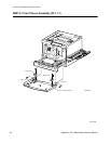
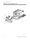
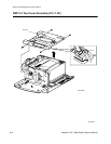
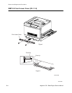
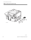
4. Position the Top Cover as shown in the figure.
5. Push the Full Stack Sensor actuator out of the way.
6. Slide the front of the Top Cover onto the front of the printer frame.
7. Reconnect P/J317 to the Operation Panel.
8. Reinstall the rear of the Top Cover onto the rear of the printer frame.
9. Reposition the Top Cover so the Exit Rolls fit through the cutouts in the left side of the Top Cover.
10. Reposition the Top Cover so the two screw holes at the rear of the Cover and the two holes at the front
of the Cover line up with the screw holes in the printer frame.
11. Use two screws to secure the front of the Top Cover to the printer frame.
12. Close the Upper Exit Cover.
13. Close the Front Cover.
14. Reinstall the Rear Cover (RRP 9.4).


