


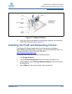

5–Installation in a VMware Environment
Installing Hardware
5-2 FE0254601-00 A
c. Carefully remove the full-height bracket by pulling it away from the
card.
d. Fit the half-height bracket while aligning the slots for the SFP+
transceivers and LEDs.
e. Fasten the half-height bracket using the screws provided.
f. Reinstall the SFP+ transceivers by pressing them in until the
transceivers clicks.
3. Power off the computer and all attached devices such as monitors, printers,
and external components.
4. Remove the server cover, and find an empty PCIe x8 bus slot. If necessary,
consult the server system manual for information about how to remove the
server cover.
5. Pull out the slot cover (if any) by removing the screw or releasing the lever.
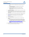
6. Grasp the adapter by the top edge, and insert it firmly into the slot
(Figure 5-1).
7. Refasten the adapter retaining bracket using the screw or lever.
8. Close the server cover.
9. Plug the appropriate Ethernet cable (either copper or optical) into the
adapter.
QLE814x adapters ship with optical transceivers already installed.
814x adapters operate only with optical transceivers sold by QLogic.
For QLE815x adapters, see the list of approved copper cables at
http://www.qlogic.com/Resources/Pages/Resources.aspx
under Cable
Support.
10. Connect the other end of the Ethernet cable to a supported switch.
11. Plug in the power cables and power up the server.