


C–Brocade CEE/FCoE Switch/Blade Configuration
Create and Configure CEE-MAP
C-4 FE0254601-00 A
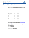
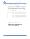
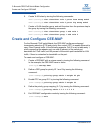
6. Create VLAN rules by issuing the following commands:
swd77(config)# vlan classifier rule 1 proto fcoe encap ethv2
swd77(config)# vlan classifier rule 2 proto fip encap ethv2
7. Create a VLAN classifier group, and add the rules from the previous step to
the group by issuing the following commands:
swd77(config)# vlan classifier group 1 add rule 1
swd77(config)# vlan classifier group 1 add rule 2
Create and Configure CEE-MAP
For the Brocade FCoE switch/blade, the CEE-MAP configures enhanced
transmission selection (ETS) and priority flow control (PFC) to enable Ethernet to
carry Fibre Channel traffic. In the following example, CoS 3 is set to table entry 1,
which means that the adapter port can use 40 percent of the switch port
bandwidth for FCoE traffic, and 60 percent of the switch port bandwidth for LAN
traffic, if there is contention for bandwidth on the port.
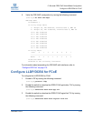
To create and configure a CEE-MAP:
1. Create a CEE-MAP with a unique name by issuing the following command.
In the example, the CEE-MAP name is demo.
(config)# cee-map demo
2. Define a CEE group for priority ID 1 and 2 by issuing the following
command:
(conf-ceemap)# priority-group-table 1 weight 40 pfc
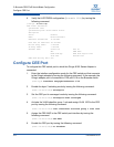
3. Enable PFC on group ID 1 by issuing the following command:
(conf-ceemap)# priority-group-table 2 weight 60
4. Define the priority group mapping (0–7) by issuing the following command:
(conf-ceemap)# priority-table 2 2 2 1 2 2 2 2
5. Exit CEE-MAP configuration mode by issuing the following command:
(conf-ceemap)# exit