


9–Offline Utilities
Fast!UTIL
FE0254601-00 A 9-5
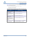
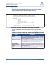
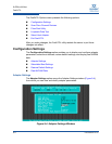
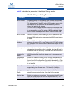
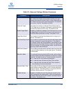
Table 9-1 describes the parameters in the Adapter Settings window.
Table 9-1. Adapter Setting Parameters
Parameter Description
BIOS Address I/O address where the QLogic BIOS code is stored when you start
the
Fast!UTIL utility or when the BIOS code is enabled by default.
This is the address of the BIOS code in ROM shadow memory. Mul-
tiple adapters can be installed in the server, but only one BIOS
instance is loaded for all adapters.
The BIOS code is loaded from the first port of the first adapter that
the server recognizes. This code is used for all remaining adapters
in the same bus or server. The version of BIOS code that is loaded
does not affect other adapters with earlier versions of BIOS code.
BIOS Revision Version of BIOS code that is loaded from the first adapter that the
server recognizes and enumerates. Each adapter in the server has
the same BIOS code revision, because only one BIOS code instance
is loaded.
Adapter Mac
Address
Ethernet MAC address for the selected adapter port. This address is
printed on the adapter SFP+ cage. This is not the CEE MAC address
that is used for LLDP communications between the adapter and the
FCoE switch.
Interrupt Level Interrupt that is used by the adapter. The interrupt level might
change when the operating system is installed. The interrupt level for
the adapter under the BIOS may be different than the interrupt level
under the operating system.
Adapter Port
Name
WWPN that identifies the QLogic adapter port in storage area net-
works.
Host Adapter
BIOS
Enables or disables the adapter BIOS. Disabling the adapter BIOS
frees space in upper memory. The adapter BIOS must be enabled
for boot-from-SAN configurations. The default is disabled. If no Fibre
Channel targets are discovered at BIOS initialization, the ROM BIOS
is not installed.
Frame Size Maximum Fibre Channel frame size supported by the adapter for
encapsulating in an Ethernet frame. The default is 2,048 bytes,
which provides maximum performance for most deployments.
Loop Reset
Delay
Time, in seconds, to delay the initiation of loop activity after the
adapter firmware resets the loop. The default is five seconds.
Spinup Delay Enables or disables the spinup delay. When enabled, the BIOS waits
up to five minutes to find the first drive (target device LUN). The
default setting is disabled.