


3–Installation in a Windows Environment
Installing Hardware
FE0254601-00 A 3-5
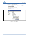
Install the Adapter
To install the adapter:
1. Record the adapter model number, which can be found on the bar code
label on the board.
2. Determine whether the server requires a full-height or a half-height adapter
bracket. The QLogic 8100 Series Adapter ships with a full-height bracket
installed and a spare half-height (low profile) bracket.
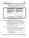
To install the half-height bracket:
a. Using the bail handle of the SFP+ transceivers, pull out the SFP+
modules.
b. Remove the two screws that hold the full-height bracket using a
Phillips #1 screw driver.
c. Carefully remove the full-height bracket by pulling it away from the
card.
d. Fit the half-height bracket while aligning the slots for the SFP+
transceivers and LEDs.
e. Fasten the half-height bracket using the screws provided.
f. Reinstall each SFP+ transceiver. Press the transceiver into the port
until it clicks in place.
3. Power off the computer and all attached devices such as monitors, printers,
and external components.
4. Remove the server cover, and find an empty PCIe x8 or larger bus slot. If
necessary, consult the server system manual for information about how to
remove the server cover.
5. Pull out the slot cover (if any) by removing the screw or releasing the lever.
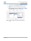
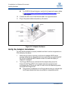
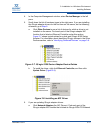
6. Grasp the adapter by the top edge, and insert it firmly into the slot
(Figure 3-3).
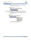
7. Refasten the adapter retaining bracket using the screw or lever.
8. Close the server cover.
9. Plug the appropriate Ethernet cable (either copper or optical) into the
adapter.
QLE814x Series Adapters ship with optical transceivers already
installed. 814x Series Adapters operate only with optical transceivers
sold by QLogic.