www.ti.com
PRODUCT PREVIEW
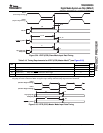
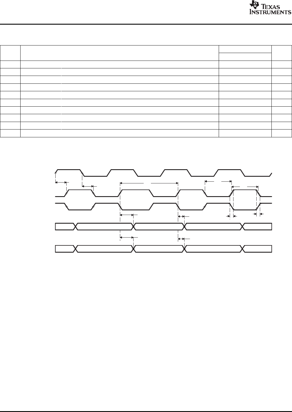
VCLK
(Positive Edge
Clocking)
VCLK
(Negative Edge
Clocking)
17
VCTL
(B)
VDATA
(C)
19
1822
21
23
24
25
26
VCLKIN
(A)
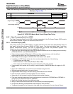
A. VCLKIN=PCLKorEXTCLK
B. VCTL=HSYNC,VSYNC,FIELD,andLCD_OE
C. VDATA=COUT[7:0],YOUT[7:0],R[7:3],G[7:2],andB[7:3]
20
20
TMS320DM355
DigitalMediaSystem-on-Chip(DMSoC)
SPRS463A–SEPTEMBER2007–REVISEDSEPTEMBER2007
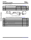
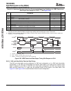
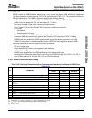
Table5-24.SwitchingCharacteristicsOverRecommendedOperatingConditionsforVPBEControland
DataOutputWithRespecttoVCLK
(1)(2)
(seeFigure5-30)
DM355
NO.PARAMETERUNIT
MINMAX
17t
c(VCLK)
Cycletime,VCLK13.33160ns
18t
w(VCLKH)
Pulseduration,VCLKhigh5.7ns
19t
w(VCLKL)
Pulseduration,VCLKlow5.7ns
20t
t(VCLK)
Transitiontime,VCLK3ns
21t
d(VCLKINH-VCLKH)
Delaytime,VCLKINhightoVCLKhigh212ns
22t
d(VCLKINL-VCLKL)
Delaytime,VCLKINlowtoVCLKlow212ns
23t
d(VCLK-VCTLV)
Delaytime,VCLKedgetoVCTLvalid4ns
24t
d(VCLK-VCTLIV)
Delaytime,VCLKedgetoVCTLinvalid0ns
25t
d(VCLK-VDATAV)
Delaytime,VCLKedgetoVDATAvalid4ns
26t
d(VCLK-VDATAIV)
Delaytime,VCLKedgetoVDATAinvalid0ns
(1)TheVPBEmaybeconfiguredtooperateineitherpositiveornegativeedgeclockingmode.Wheninpositiveedgeclockingmode,the
risingedgeofVCLKisreferenced.Wheninnegativeedgeclockingmode,thefallingedgeofVCLKisreferenced.
(2)VCLKIN=PCLKorEXTCLK.NotethatiftheCCDCisused,thePCLKfrequencymustbelessthanorequaltohalftheVPSSclock
frequency—i.e.,PCLK≤SYSCLK4/2.
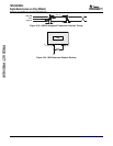
Figure5-30.VPBEControlandDataOutputTimingWithRespecttoVCLK
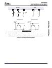
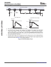
5.9.2.4DACandVideoBufferElectricalData/Timing
TheDACandvideobuffercanbeconfiguredinaDAConlyconfigurationorinaDACandvideobuffer
configuration.IntheDAConlyconfigurationtheinternalvideobufferisnotusedandanexternalvideo
bufferisattachedtotheDAC.IntheDACandvideobufferconfiguration,theDACandinternalvideo
bufferarebothusedandaTVcablemaybeattacheddirectlytotheoutputofthevideobuffer.See
Figure5-31andFigure5-32forrecommencedcircuitsforeachconfiguration.
PeripheralInformationandElectricalSpecifications 124SubmitDocumentationFeedback


