www.ti.com
PRODUCT PREVIEW
2.4.3AsynchronousExternalMemoryInterface(AEMIF)
TMS320DM355
DigitalMediaSystem-on-Chip(DMSoC)
SPRS463A–SEPTEMBER2007–REVISEDSEPTEMBER2007
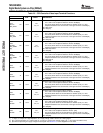
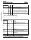
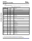
Table2-8.AnalogVideoTerminalFunctions
TERMINAL
TYPE
(1)
OTHER
(2)
DESCRIPTION
NAMENO.
VideoDAC:Referencevoltageoutput(0.45V,0.1uFtoGND).WhentheDACisnot
VREFJ7AI/O/Z
used,theVREFsignalshouldbeconnectedtoV
SS
.
VideoDAC:PrevideobufferDACoutput(1000ohmtoVFB).WhentheDACisnot
IOUTE1AI/O/Z
used,theIOUTsignalshouldbeconnectedtoV
SS
.
VideoDAC:Externalresistor(2550OhmstoGND)connectionforcurrentbias
IBIASF2AI/O/Zconfiguration.WhentheDACisnotused,theIBIASsignalshouldbeconnectedto
V
SS
.
VideoDAC:PrevideobufferDACoutput(1000OhmstoIOUT,1070Ohmsto
VFBG1AI/O/Z
TVOUT).WhentheDACisnotused,theVFBsignalshouldbeconnectedtoV
SS
.
VideoDAC:AnalogCompositeNTSC/PALoutput(SeeFigure5-31andFigure5-32for
TVOUTF1AI/O/ZVcircuitconnection).WhentheDACisnotused,theTVOUTsignalshouldbeleftasa
NoConnectorconnectedtoV
SS
.
VideoDAC:Analog1.8Vpower.WhentheDACisnotused,theV
DDA18_DAC
signal
V
DDA18_DAC
L7PWR
shouldbeconnectedtoV
SS
.
VideoDAC:Analog1.8Vground.WhentheDACisnotused,theV
SSA_DAC
signal
V
SSA_DAC
L8GND
shouldbeconnectedtoV
SS
.
(1)I=Input,O=Output,Z=Highimpedance,S=Supplyvoltage,GND=Ground,A=Analogsignal.SpecifiestheoperatingI/Osupply
voltageforeachsignal.SeeSection5.3,PowerSuppliesformoredetail.
(2)PD=pull-down,PU=pull-up.(Topullupasignaltotheoppositesupplyrail,a1kΩresistorshouldbeused.)
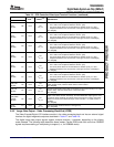
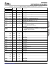
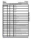
TheAsynchronousExternalMemoryInterface(AEMIF)signalssupportAEMIF,NAND,andOneNAND.
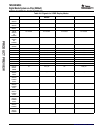
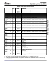
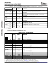
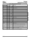
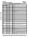
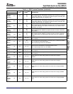
Table2-9.AsynchronousEMIF/NAND/OneNANDTerminalFunctions
TERMINAL
TYPE
(1)
OTHER
(2)(3)
DESCRIPTION
NAMENO.
AsyncEMIF:Addressbusbit[13]
EM_A13/
PDGIO:GIO[67]
GIO067/V19I/O/Z
V
DD
System:BTSEL[1:0]sampledatpower-on-resettodeterminebootmethod.Used
BTSEL[1]
todrivebootstatusLEDsignal(activelow)inROMbootmodes.
EM_A12/AsyncEMIF:Addressbusbit[12]
PD
GIO066/U19I/O/ZGIO:GIO[66]
V
DD
BTSEL[0]System:BTSEL[1:0]sampledatpower-on-resettodeterminebootmethod.
AsyncEMIF:Addressbusbit[11]
EM_A11/
PUGIO:GIO[65]
GIO065/R16I/O/Z
V
DD
AECFG[3:0]sampledatpower-on-resettoAECFGconfiguration.AECFG[3]sets
AECFG[3]
defaultforPinMux2_EM_D15_8:AEMIFdefaultbuswidth(16or8bits)
AsyncEMIF:Addressbusbit[10]
EM_A10/GIO:GIO[64]
PU
GIO064/R18I/O/ZAECFG[3:0]sampledatpower-on-resettoAECFGconfiguration.AECFG[2:1]
V
DD
AECFG[2]setsdefaultforPinMux2_EM_BA0:AEMIFEM_BA0definition(EM_BA0,
EM_A14,GIO[054],rsvd)
AsyncEMIF:Addressbusbit[09]
EM_A09/GIO:GIO[63]
PD
GIO063/P17I/O/ZAECFG[3:0]sampledatpower-on-resettoAECFGconfiguration.AECFG[2:1]
V
DD
AECFG[1]setsdefaultforPinMux2_EM_BA0:AEMIFEM_BA0definition(EM_BA0,
EM_A14,GIO[054],rsvd)
AsyncEMIF:Addressbusbit[08]
GIO:GIO[62]
EM_A08/
PD
AECFG[0]setsdefaultfor:
GIO062/T19I/O/Z
V
DD
AECFG[0]•PinMux2_EM_A0_BA1:AEMIFaddresswidth(OneNANDorNAND)
•PinMux2_EM_A13_3:AEMIFaddresswidth(OneNANDorNAND)
EM_A07/AsyncEMIF:Addressbusbit[07]
P16I/O/ZV
DD
GIO061GIO:GIO[61]
(1)I=Input,O=Output,Z=Highimpedance,S=Supplyvoltage,GND=Ground,A=Analogsignal.
(2)SpecifiestheoperatingI/Osupplyvoltageforeachsignal.SeeSection5.3,PowerSuppliesformoredetail.
(3)PD=pull-down,PU=pull-up.(Topullupasignaltotheoppositesupplyrail,a1kΩresistorshouldbeused.)
DeviceOverview 18SubmitDocumentationFeedback


