


www.ti.com
PRODUCT PREVIEW
5.5OscillatorsandClocks
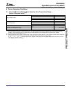
5.5.1MXI1(24-MHz)Oscillator
Crystal
24MHzor
36MHz
C1 C2
MXI1/CLKIN
MXO1 V
SS_MX1
0.1 F
1 F
L1
V
DDA_PLL1
V
SSA_PLL1
C
L
C
1
C
2
(C
1
C
2
)
TMS320DM355
DigitalMediaSystem-on-Chip(DMSoC)
SPRS463A–SEPTEMBER2007–REVISEDSEPTEMBER2007
hastwooscillatorinput/outputpairs(MXI1/MXO1andMXI2/MXO2)usablewithexternalcrystalsor
ceramicresonatorstoprovideclockinputs.Theoptimalfrequenciesforthecrystalsare24MHz
(MXI1/MXO1)and27MHz(MXI2/MXO2).Optionally,theoscillatorinputsareconfigurableforusewith
externalclockoscillators.Ifexternalclockoscillatorsareused,tominimizetheclockjitter,asingleclean
powersupplyshouldpowerboththeandtheexternaloscillatorcircuitandtheminimumCLKINriseand
falltimesmustbeobserved.Theelectricalrequirementsandcharacteristicsaredescribedinthissection.
ThetimingparametersforCLKOUT[3:1]arealsodescribedinthissection.Thehasthreeoutputclockpins
(CLKOUT[3:1]).SeeSection3.5andSection3.6formoreinformationonCLKOUT[3:1].
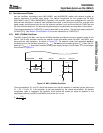
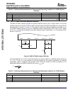
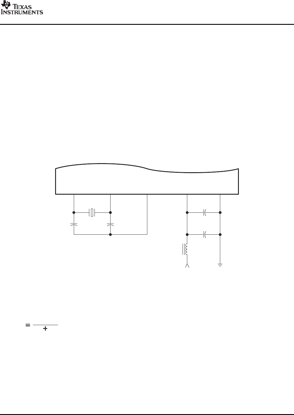
TheMXI1(typically24MHz,canalsobe36MHz)oscillatorprovidestheprimaryreferenceclockforthe
device.Theon-chiposcillatorrequiresanexternalcrystalconnectedacrosstheMXI1andMXO1pins,
alongwithtwoloadcapacitors,asshowninFigure5-5.Theexternalcrystalloadcapacitorsmustbe
connectedonlytotheoscillatorgroundpin(V
SS_MX1
).Donotconnecttoboardground(V
SS
).Also,thePLL
powerpin(V
DDA_PLL1
)shouldbeconnectedtothepowersupplythroughaferritebead,L1intheexample
circuitshowninFigure5-5.
Figure5-5.MXI1(24-MHz)Oscillator
Theloadcapacitors,C1andC2,shouldbechosensuchthattheequationissatisfied(typicalvaluesare
C1=C2=10pF).CLintheequationistheloadspecifiedbythecrystalmanufacturer.Alldiscrete
componentsusedtoimplementtheoscillatorcircuitshouldbeplacedascloseaspossibletothe
associatedoscillatorpins(MXI1andMXO1)andtotheV
SS_MX1
pin.
SubmitDocumentationFeedbackPeripheralInformationandElectricalSpecifications99