


www.ti.com
PRODUCT PREVIEW
2.4.15SystemConfigurationInterface
TMS320DM355
DigitalMediaSystem-on-Chip(DMSoC)
SPRS463A–SEPTEMBER2007–REVISEDSEPTEMBER2007
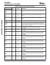
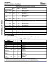
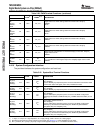
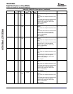
Table2-20.PWMTerminalFunctions(continued)
TERMINAL
TYPE
(1)
OTHER
(2)(3)
DESCRIPTION
NAMENO.
COUT3-
B6/DigitalVideoOut:VENCsettingsdeterminefunctionGIO:GIO[077]
GIO077/E3I/O/ZV
DD_VOUT
PWM2C
PWM2C/RTO2
RTO2
COUT2-
B5/DigitalVideoOut:VENCsettingsdeterminefunctionGIO:GIO[076]
GIO076/E4I/O/ZV
DD_VOUT
PWM2D
PWM2D/RTO3
RTO3
COUT1-
B4/DigitalVideoOut:VENCsettingsdeterminefunctionGIO:GIO[075]
F3I/O/ZV
DD_VOUT
GIO075/PWM3A
PWM3A
COUT0-
B3/DigitalVideoOut:VENCsettingsdeterminefunctionGIO:GIO[074]
F4I/O/ZV
DD_VOUT
GIO074/PWM3B
PWM3B
FIELD/
VideoEncoder:FieldidentifierforinterlaceddisplayformatsGIO:GIO[070]
GIO070/
H4I/O/ZV
DD_VOUT
DigitalVideoOut:R2
R2/
PWM3C
PWM3C
EXTCLK/
VideoEncoder:Externalclockinput,usedifclockrates>27MHzareneeded,
GIO069/PD
G3I/O/Ze.g.74.25MHzforHDTVdigitaloutputGIO:GIO[069]DigitalVideoOut:B2
B2/V
DD_VOUT
PWM3D
PWM3D
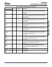
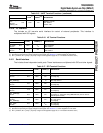
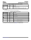
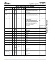
Theprovidesinterfacesforsystemconfigurationandbootload.
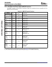
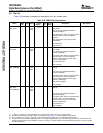
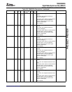
Table2-21.System/BootTerminalFunctions
TERMINAL
TYPE
(1)
OTHER
(2)(3)
DESCRIPTION
NAMENO.
AsyncEMIF:Addressbusbit13
EM_A13/
PDGIO:GIO[067]
GIO067/V19I/O/Z
V
DD
System:BTSEL[1:0]sampledatpower-on-resettodeterminebootmethod.Used
BTSEL[1]
todrivebootstatusLEDsignal(activelow)inROMbootmodes.
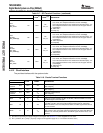
EM_A12/AsyncEMIF:Addressbusbit12
PD
GIO066/U19I/O/ZGIO:GIO[066]
V
DD
BTSEL[0]System:BTSEL[1:0]sampledatpower-on-resettodeterminebootmethod.
AsyncEMIF:Addressbusbit11
EM_A11/GIO:GIO[065]
PU
GIO065/R16I/O/ZSystem:AECFG[3:0]sampledapower-on-resettosetAEMIFconfiguration.
V
DD
AECFG[3]AECFG[3]setsdefaultfoPinMux2.EM_D15_8.AEMIFdefaultbuswidth(16or8
bits).
AsyncEMIF:Addressbusbit10
EM_A10/GIO:GIO[064]
PU
GIO064/R18I/O/ZSystem:AECFG[3:0]sampledapower-on-resettosetAEMIFconfiguration.
V
DD
AECFG[2]AECFG[2:1]setsdefaultfoPinMux2.EM_BA0.AEMIFEM_BA0definition:
(EM,_BA0,EM_A14,GOP[054],rsvd)
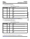
AsyncEMIF:Addressbusbit09
EM_A09/GIO:GIO[063]
PD
GIO063/P17I/O/ZSystem:AECFG[3:0]sampledapower-on-resettosetAEMIFconfiguration.
V
DD
AECFG[1]AECFG[2:1]setsdefaultfoPinMux2.EM_BA0.AEMIFEM_BA0definition:
(EM,_BA0,EM_A14,GOP[054],rsvd)
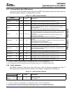
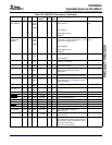
(1)I=Input,O=Output,Z=Highimpedance,S=Supplyvoltage,GND=Ground,A=Analogsignal.
(2)SpecifiestheoperatingI/Osupplyvoltageforeachsignal.SeeSection5.3,PowerSuppliesformoredetail.
(3)PD=pull-down,PU=pull-up.(Topullupasignaltotheoppositesupplyrail,a1kΩresistorshouldbeused.)
DeviceOverview 34SubmitDocumentationFeedback