


www.ti.com
PRODUCT PREVIEW
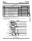
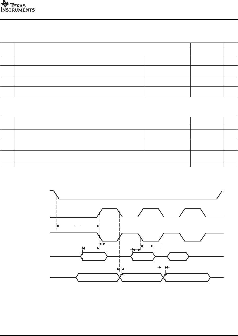
SPI_CLK
(ClockPolarity=0)
SPI_CLK
(ClockPolarity=1)
SPI_DI
(Input)
SPI_DO
(Output)
13
MSBIN DATA LSBIN
LSBOUTMSBOUT
DATA
17
15
14
16
SPI_EN
19
18
TMS320DM355
DigitalMediaSystem-on-Chip(DMSoC)
SPRS463A–SEPTEMBER2007–REVISEDSEPTEMBER2007
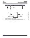
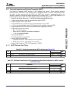
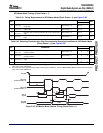
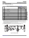
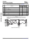
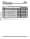
SPIMasterModeTimings(ClockPhase=1)
Table5-31.TimingRequirementsforSPIMasterMode[ClockPhase=1](seeFigure5-38)
DM355
NO.UNIT
MINMAX
Setuptime,SPI_DI(input)validbeforeSPI_CLK(output)
13t
su(DIV-CLKL)
ClockPolarity=0.5P+3ns
risingedge
Setuptime,SPI_DI(input)validbeforeSPI_CLK(output)
14t
su(DIV-CLKH)
ClockPolarity=1.5P+3ns
fallingedge
Holdtime,SPI_DI(input)validafterSPI_CLK(output)rising
15t
h(CLKL-DIV)
ClockPolarity=0.5P+3ns
edge
Holdtime,SPI_DI(input)validafterSPI_CLK(output)falling
16t
h(CLKH-DIV)
ClockPolarity=1.5P+3ns
edge
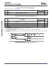
Table5-32.SwitchingCharacteristicsOverRecommendedOperatingConditionsforSPIMasterMode
[ClockPhase=1](seeFigure5-38)
DM355
NO.PARAMETERUNIT
MINMAX
Delaytime,SPI_CLK(output)fallingedgetoSPI_DO
17t
d(CLKL-DOV)
ClockPolarity=0-45ns
(output)transition
Delaytime,SPI_CLK(output)risingedgetoSPI_DO
18t
d(CLKH-DOV)
ClockPolarity=1-45ns
(output)transition
Delaytime,SPI_EN[1:0](output)fallingedgetofirstSPI_CLK(output)risingorfalling2P+.5C
19t
d(ENL-CLKH/L)
(1)
ns
edge
(1)
20t
d(CLKL/H-DOHz)
Delaytime,SPI_CLK(output)fallingorrisingedgetoSPI_DO(output)highimpedanceP
(2)(2)
ns
(1)ThedelaytimecanbeadjustedusingtheSPImoduleregisterC2TDELAY.SeetheTMS320DM355DMSoCSerialPeripheralInterface
(SPI)User'sGuide(SPRUED4).
(2)ThedelaytimecanbeadjustedusingtheSPImoduleregisterT2CDELAY.SeetheTMS320DM355DMSoCSerialPeripheralInterface
(SPI)User'sGuide(SPRUED4).
Figure5-38.SPIMasterModeExternalTiming(ClockPhase=1)
SubmitDocumentationFeedbackPeripheralInformationandElectricalSpecifications133