


-.
INSTALLATION-OK 16 KSU & PCB
SECTION 100-816-205
MARCH 1993
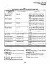
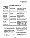
TABLE 5-H
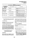
KCDU CONTROLS, INDICATORS, AND CONNECTORS
CONTROL/INDICATOR/
CONNECTOR
TYPE OF COMPONENT DESCRIPTION
(Figure 5-21)
CO line circuit 1 Red LED Lights to indicate CO line circuit 1 is in
Indicator CD51 7 operation.
CO line circuit 2 Red LED Lights to indicate CO line circuit 2 is in
Indicator CD61 7 operation.
J7 Connectors
Modular connector Interface connector for CO line circuits,
1 and 2.
PAD Switch SW501
Two-position slide Enables 3dB signal level drop for CO line
circuit 1 (when set in PAD position).
PAD Switch SW601
Two-position slide Enables 3dB signal level drop for CO line
circuit 2 (when set in PAD position).
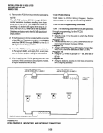
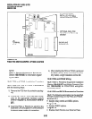
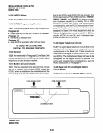
4) After installing the KCDU, gently pull the PCB
outward. If the connectors are properly mated,
a slight resistance will be felt.
13.30 KCDU Wiring
13.31
Refer to KCDU Wiring Diagram in Section
100-816-208
for wiring/interconnecting details.
13.40 KCDU Programming Overview
13.41
See the PCOU programming overview and
the PDKU overview in this chapter for KCDU pro-
gramming information. When running
Program 03
for the KCDU slot(s), specify code 65 if the KCDU
does not support OCA or PDIU-DI telephones or
code 66 if the KCDU supports OCA or PDIU-DI
telephones. Do not specify code 11,61,62, or 64.
14 DTMF RECEIVEWABR TONE
DETECTOR UNIT (K4RCU)
14.00 General
14.01
The K4RCU must be installed to recognize
Dual-Tone Multi-Frequency (DTMF) tones gener-
ated by a standard telephone (or any other device
connected to a standard telephone circuit) and it is
required for Direct Inward System Access (DISA)
calls. The K4RCU can only be installed in the Base
Unit. The K4RCU circuits are also used to detect
busy tone for the Automatic Busy Redial (ABR)
feature and must be installed to‘ allow ABR to
operate.
14.10 K4RCU Configuration
14.11
The K4RCU does not have to be configured
for operation.
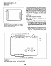
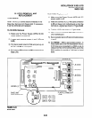
14.20 K4RCU Installation Procedure
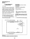
14.21
Install the K4RCU in accordance with the
following steps (Figure 5-22).
1) Remove the PCB from its protective packaging.
2) Make sure that the power supply switch is
OFF.
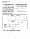
3) Making sure that the component side of the
K4RCU is facing up toward the power supply,
plug the K4RCU
P602A
and
P602B
female
connectors into the
P2A
and
P2B
(K4RCU)
connectors on the motherboard.
5-33