


INSTALLATION-OK16 KSU & PCB
SECTION 100-816-205
MARCH 1993
PART I. KSU INSTALLATION
1 GENERAL
1.00
This chapter provides the instructions nec-
essary to mount both the STRATA DKI 6 Base Key
Service Unit and the Expansion Key Service Unit.
Instructions are also provided on how to test,
remove, and replace the power supply and base
unit CO line interface subassembly.
2 KEY SERVICE UNIT MOUNTING
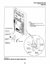
2.00 Mounting Surface Considerations
2.01
The Base Key Service Unit and the optional
Expansion Key Service Unit are both designed to
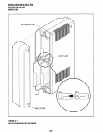
be mounted on a wall or other vertical surface. It is
recommended to use Method 1 or 2 in Figure 5-2
(see Note).
NOTE:
If mounting the KSU directly to a wall, be sure
to align screws with studs behind the wall; if
using a hard board between the KSU and the
wall, installscrews first to the hardboard, and
then secure the hard board to the wall, mak-
ing certain that scre ws are aligned with studs.
2.10 Mounting Preparation
1)
2)
3)
4)
5)
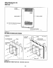
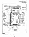
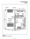
Loosen the screws on the front cover and the
side cover of the Base Key Service Unit, and
remove the covers (Figure 5-l).
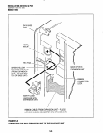
Move the
SW1
Memory Battery Backup strap
on the motherboard to the ON position (Figure
5-3).
If applicable, install the K4RCU into the Base
Key Service Unit (see Paragraph 14).
If applicable, install the KSTU into the Base
Key Service Unit (see Paragraph 6).
Plug the AC power cable into an outlet (Figure
5-3).
l
The “AC” LED on the power supply will light
green (If not, refer to the Fault Finding sec-
tion later in this manual).
6) Turn the switch on the power supply to the ON
position (Figure 5-3).
l
The “DC” LED on the power supply will light
green. (If not, refer to the Fault Finding
section later in this manual).
7)
Using avoltmeterorother device which checks
voltage, measure the voltages referenced to
frame ground (FG) at the
DC OUT connector
pins
(test points) located on the motherboard
(Figure 5-3). The voltages should fall within
the ranges below. If the voltages do not fall
within the ranges, unplug the DC power pins
from the DC OUT connector and measure
again at the same location; if the ranges
remain unacceptable, replace the power sup-
ply (see Paragraph 3).
l
Yellow-Green, Black, and Green Wires: OV
l
Yellow Wire: -24V
l
Range: -26.3V - -27.8V
l
Red Wire: 5V
l
Range: 4.5V - 5.5V
l
Blue Wire: -5V
l
Range: -4.5V - -5.5V
2.20 Mounting the Base Key Service Unit
1) Make sure the power supply switch is turned
OFF.
2) Place the Base Key Service Unit on the de-
sired location on the mounting surface and
mark the location of the four screw holes
(there is one on each corner). See Figure 5-2.
NOTE:
Make sure the location of the Base Key
Service Unit meets the minimum clearance
requirements specified in Figure 2-2 in
Chapter 2.
3) Drill holes on these marks.
NOTE:
If mounting the KS0 directly to a wall, be sure
to align screws with studs behind the wall; if
using a hard board between the KSU and the
wall, installscrews first to the hard board, and
then secure the hard board to the wall, mak-
ing certain that screws are aligned with studs.
5-l