


1 INTRODUCTION
1 .OO This chapter offers guidelines and consider-
ations on how to configure a STRATA DK8/DK16
system, which can support a wide variety of sta-
tions and peripherals.
2 SYSTEM CAPACITY
2.00 Total System Capacity
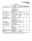
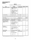
2.01 The STRATA DK8/DK16 systems have a
modular design which allows them to support a
number of station and CO line configurations. The
main component of each system is the Key Ser-
vice Unit. The DK8 KSU can have up to IO stations
and four CO lines. The DK16 Base Key Service
Unit can have up to 12 stations and four CO lines.
An Expansion Key Service Unit can be added to
the DK16 to increase the station capacity to 20 and
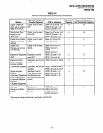
the CO line capacity to eight. Station and CO line
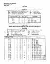
configurations are shown in Table 3-A (for DK8)
and Table 3-B (for DK16).
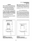
2.10 The DK8 Key Service Unit
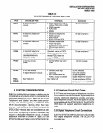
2.11 Station and CO Lines. The DK8 Key Service
Unit comes standard with four digital telephone
circuits (ports) and two CO line circuits (Table
3-C). An optional printed circuit board called the
QCDU can be added to the KSU to provide one CO
line circuit and two digital telephone circuits. A
maximum of two QCDUs may be added to provide
a total of four additional digital telephone circuits
and two additional CO line circuits. Another op-
tional printed circuit board called the QSTU can be
added to the DK8 KSU to provide two standard
telephone circuits.
2.12 Peripherals. The DK8 Key Service Unit can
support a number of peripherals, which are not
considered as stations and do not affect the maxi-
mum station and CO line capacities. A customer-
supplied Music-on-hold source, optional reserve
power battery and charger, a customer-supplied
emergency standard telephone for system power
failure occurrences and an amplifier with speaker
for paging and night ringing can all be connected
to the Key Service Unit (Table 3-C). A relay contact
is also provided to control one of the following
INSTALLATION-CONFIGURATION
SECTION 100-816-203
MARCH 1993
peripherals: Music-on-hold source, night bell, or
page amplifier mute control.
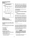
2.20 The DK16 Base Key Service Unit
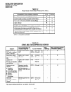
2.21 Station and CO Lines. The DKI 6 Base Key
Service Unit comes standard with eight digital
telephone circuits (ports) and four CO line circuits
(Table 3-D). An optional printed circuit board called
the KSTU can be added to the unit to provide four
standard telephone circuits (ports).
2.22 Peripherals. The DK16 Base Key Service
Unit can support a number of peripherals, which
are not considered as stations and do not affect
the maximum station and CO line capacities. A
customer-supplied Music-on-hold source, cus-
tomer-supplied separate background music
source, customer-supplied reserve power batter-
ies, a customer-supplied emergency standard
telephone for system power failure occurrences
and an amplifier with speaker for paging and night
ringing can all be connected to the Base Key
Service Unit (Table 3-D). A relay contact is also
provided to control one of the following peripher-
als: Music-on-hold source, night bell, or Page
Amplifier mute control.
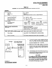
2.30 The DK16 Expansion Key Service Unit
2.31 Station and CO Lines. The optional DK16
Expansion Key Service Unit has four universal
slots which can support a maximum of four CO
lines and eight stations. Printed circuit boards
(PCBs) that support CO lines and can be installed
in the Expansion Unit are the PCOU and KCDU
(Table 3-E). PCBs that can support stations and be
installed in the Expansion Unit are the PDKU,
PEKU, PSTU, PESU, and KCDU.
2.32 Peripherals. The Expansion Unit can sup-
port either a PIOU or PIOUS PCB, which both
provide, among other features, Station Message
Detail Recording (SMDR), an interface for a local
programming terminal, and connectors for an in-
ternal modem (IMDU) for remote maintenance
and administration (Table 3-F). Any device that
connects to the PIOU or PIOUS should not be
considered a station and does not affect the
system’s station capacity.
3-1